Virtual private LAN service using a multicast protocol

Active Publication Date: 2008-03-04
CORRIGENT CORP
View PDF32 Cites 319 Cited by
  • Summary
  • Abstract
  • Description
  • Claims
  • Application Information

AI Technical Summary

Benefits of technology

[0015]The present invention seeks to provide improved mechanisms for packet flooding in virtual private networks (VPNs), particularly Ethernet VPNs. For this purpose, in preferred embodiments of the present invention, virtual bridges in a layer-2 VPN take advantage of the inherent multicast capabilities of existing netwo...

Problems solved by technology

VPLS networks are still in the development stage, and there ...

Method used


Image

  • Virtual private LAN service using a multicast protocol
  • Virtual private LAN service using a multicast protocol
  • Virtual private LAN service using a multicast protocol

Examples


Embodiment Construction

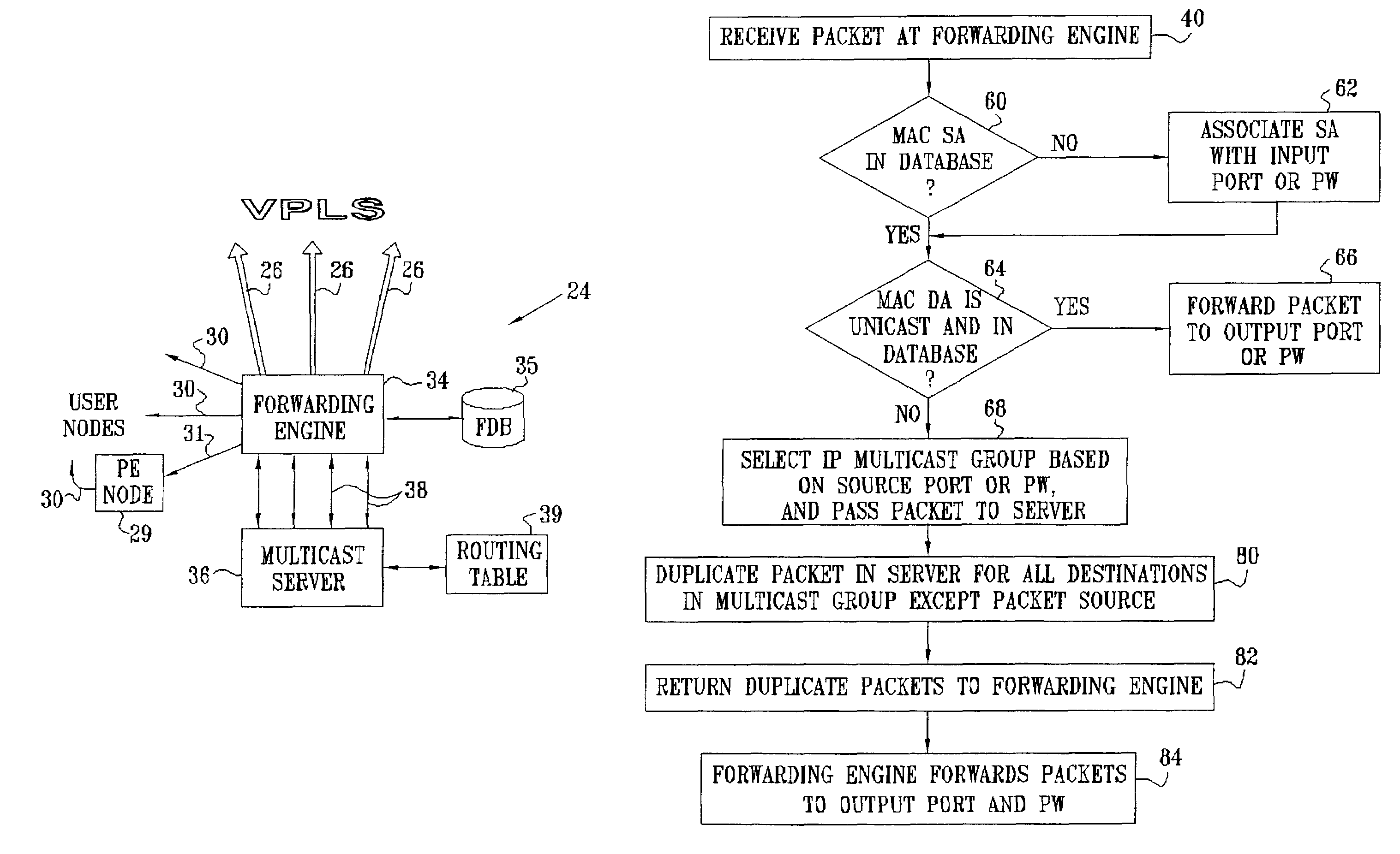
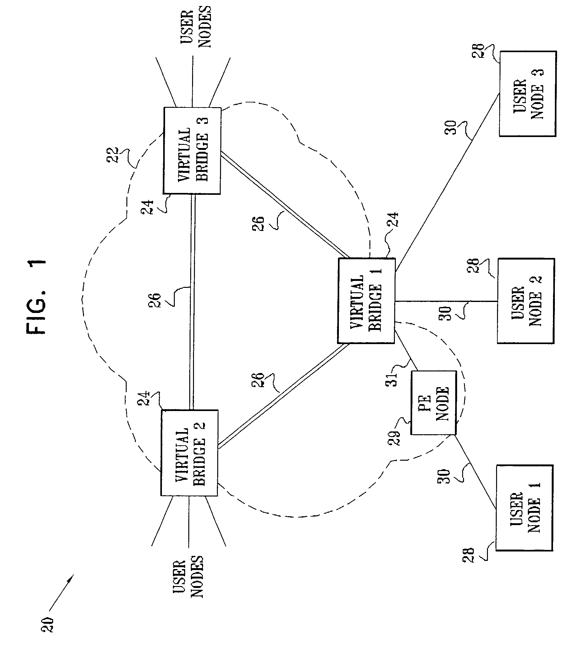
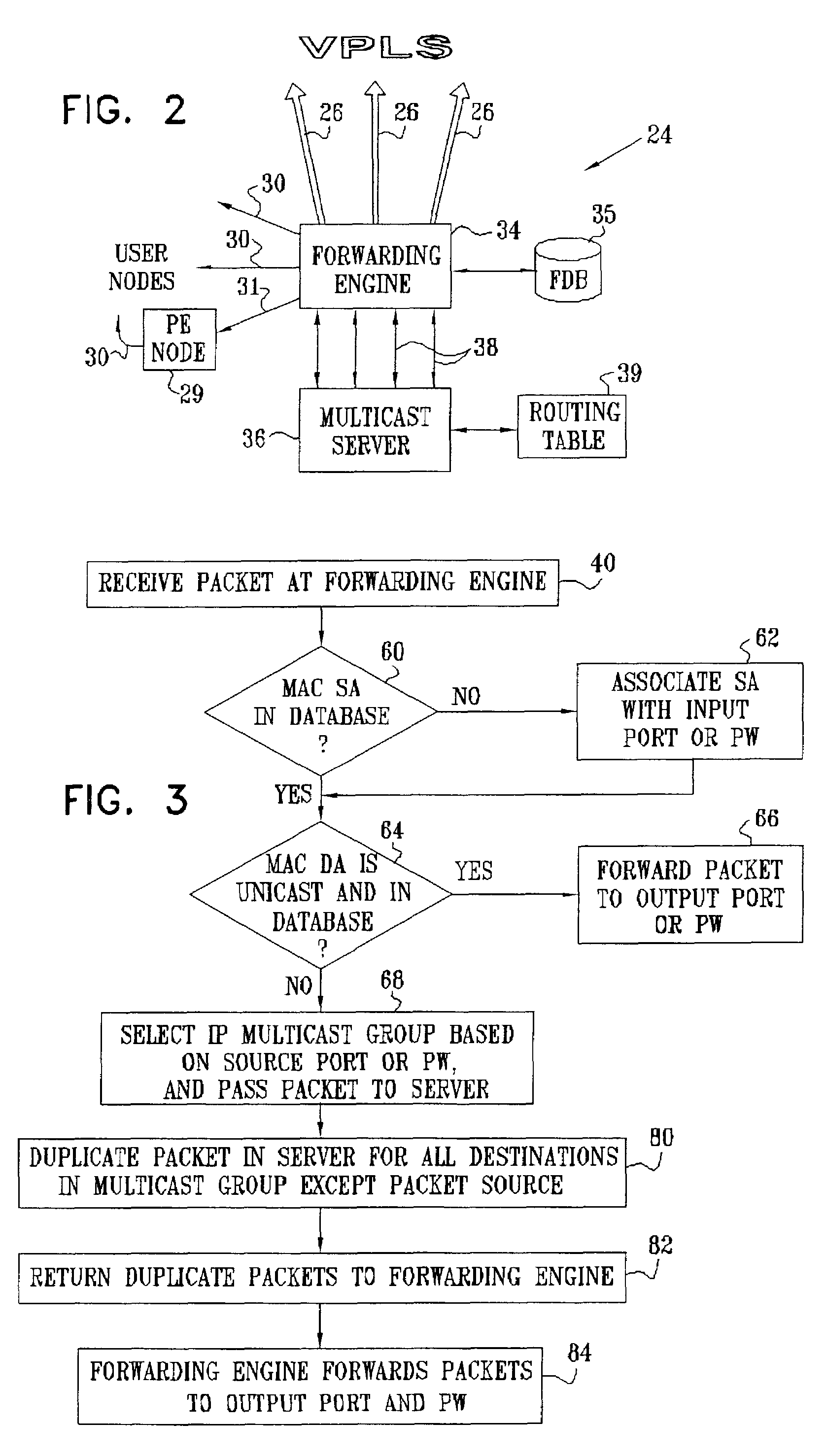
[0048]FIG. 1 is a block diagram that schematically illustrates a virtual private network (VPN) 20, in accordance with a preferred embodiment of the present invention. VPN 20 is built around a virtual private LAN service (VPLS), operating within a network 22, typically an IP or MPLS network. The VPLS is based on virtual bridges 24, or VPLS-capable PEs, which are connected by PW 26, through network 22. Virtual bridges 24 also have connections either directly to user nodes 28, or CEs, via Ethernet physical interfaces 30, or via virtual PW connections 31 to a “simple” PE node 29, which in turn is connected to the user node via physical interfaces 30. PE node 29 is able to translate physical user Ethernet ports into virtual connections, as specified in the above-mentioned draft by Martini, but does not necessarily perform bridging operations. Typically, a simple PE node provides aggregated access for many users to network 22, and the network includes many such PEs. These PE nodes are omi...


PUM


Abstract

A method for data broadcast over a network includes receiving at a virtual bridge a data packet to be flooded over the network, and passing the data packet from the virtual bridge to a multicast-capable router, along with a broadcast indication. Responsive to the broadcast indication, the router determines a group of destination addresses to which the packet should be multicast, and creates copies of the packet for transmission over the network to the destination addresses in the group.

Description

FIELD OF THE INVENTION[0001]The present invention relates generally to communication networks, and specifically to methods and systems for providing virtual private LAN services (VPLS).BACKGROUND OF THE INVENTION[0002]Local Area Networks (LANs) connect computing systems together. LANs of all types can be connected together using Media Access Control (MAC) bridges, as set forth in the “IEEE Standard for Information Technology, Telecommunications and Information Exchange between Systems, Local and Metropolitan Area Networks, Common Specifications, Part 3: Media Access Control (MAC) Bridges,” published as ANSI / IEEE Standard 802.1D (1998), which is incorporated herein by reference. The 802.1D standard is available at standards.ieee.org / catalog / IEEE802.1.html.[0003]Each computing system connects to a LAN through a MAC device. MAC bridges that implement the 802.1D standard allow MAC devices attached to physically separated LANs to appear to each other as if they were attached to a single ...

Claims


Application Information

Patent Timeline
IPC IPC(8): H04L12/28H04L12/18H04L12/46H04L12/56
CPCH04L12/1836H04L12/1886H04L12/462H04L12/4633H04L12/4641H04L45/50
Inventor ZELIG, DAVIDBRUCKMAN, LEONMOR, GALMENAHEMI, ZVI
Owner CORRIGENT CORP
Why Eureka
Try Eureka