Adaptive beamforming methods and systems that enhance performance and reduce computations

a beamforming and adaptive technology, applied in the field of wireless communication systems, can solve the problems of inability to identify the signal of interest, inability to adapt to the transmitted signal, and resultant estimation of the transmitted signal is then in error, so as to facilitate optimization of spatial information, reduce computational complexity, and facilitate single matrix inversion

Active Publication Date: 2008-03-04
CALLAHAN CELLULAR L L C
View PDF6 Cites 73 Cited by
  • Summary
  • Abstract
  • Description
  • Claims
  • Application Information

AI Technical Summary

Benefits of technology

[0012]The present invention is directed to beamforming concepts which include a) progressive beamforming that substantially reduces computational complexity, b) current and delayed versions of data-carrying signals that facilitate optimization of spatial information, and c) time-of-arrival information that facilitates a single matrix inversion which substantially reduces the complexity of conventional beamforming computations.

Problems solved by technology

Although this beamforming approach provides an optimal solution for signals received at a selected time-of-arrival, these may not be the signals of interest.
The resultant estimate of the transmitted signal is then in error because it ignores relevant signal energy that arrived at times other than the selected time-of-arrival.
Conventional adaptive beamforming approaches face additional problems when a system's multipath delays exceed the toleration capability of the signal's modulation format.
In systems that incorporate adaptive beamforming antennas, however, it is difficult to integrate such equalizers with the beamforming algorithms.
Implementing the equalization prior to beamforming robs the equalization process of the beamforming gains, thereby causing inaccurate equalization.
Adding the equalization after beamforming is problematic because the beamforming will treat signals with excess multipath delay as interference and therefore attempt to reject them.
This, however, leads to substantially increased computational requirements because the required computations are multiplied by the number of paths to be processed.
Unfortunately, this generally increases the convergence time of the optimization so that the resulting processing gains are substantially less in the early portion of the received signal.
This approach is thus particularly problematic for burst communication systems.

Method used


Image

  • Adaptive beamforming methods and systems that enhance performance and reduce computations
  • Adaptive beamforming methods and systems that enhance performance and reduce computations
  • Adaptive beamforming methods and systems that enhance performance and reduce computations

Examples


Embodiment Construction

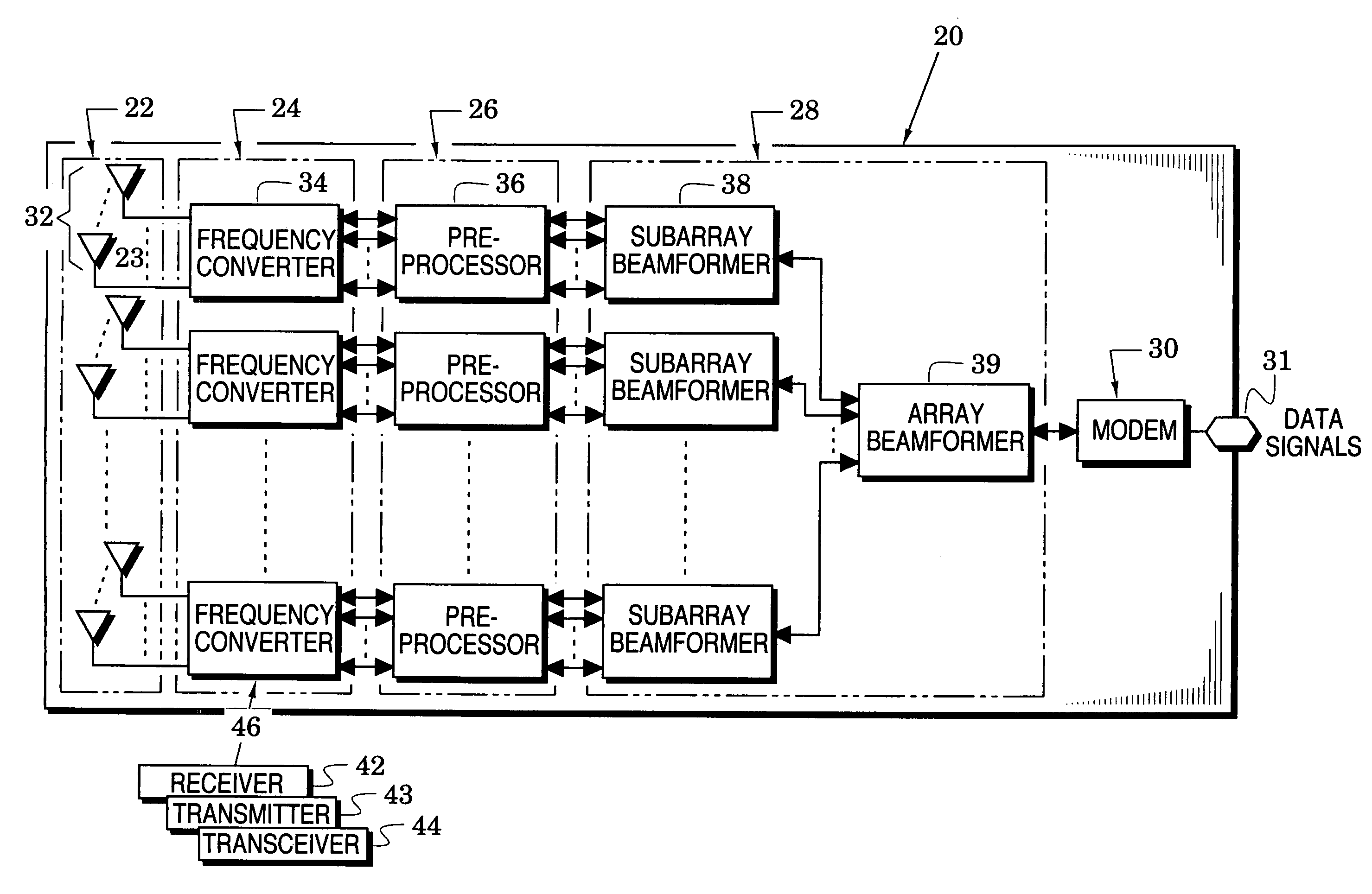
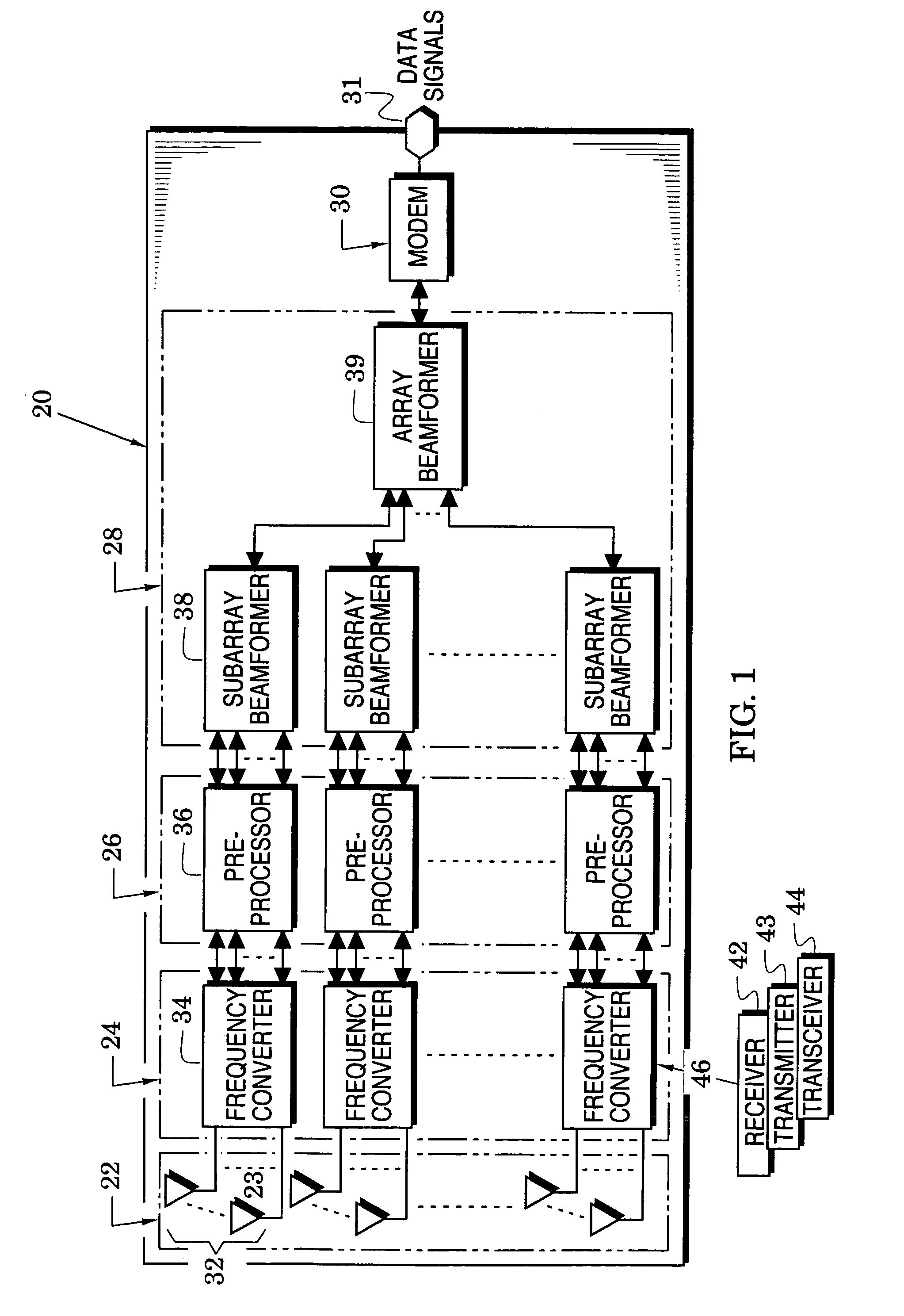
[0017]Attention is initially directed to FIG. 1 which illustrates a wireless communication system embodiment 20 that includes an array 22 of antennas 23, a radio-frequency (RF) frequency converter 24, a preprocessor 26, a beamformer 28 and a modulator / demodulator (modem) 30. The RF converter is coupled to the antenna array 22 and the preprocessor 26 couples the RF converter to the beamformer 28. The modem 30 is coupled between the beamformer and a system data port 31.

[0018]In at least one embodiment of the invention, the antenna array 22 is partitioned into subarrays 32, the RF converter 24 is partitioned into frequency converters 34, the preprocessor 26 is partitioned into preprocessors 36 and the beamformer 28 is partitioned into subarray beamformers 38 and an array beamformer 39. With reference to these element partitions, each frequency converter 34 is coupled to a respective subarray 32 of antennas 23 and each of the preprocessors 36 is coupled between a respective frequency co...


PUM


Abstract

Wireless communication systems and methods are provided that a) enable progressive beamforming with antenna arrays and subarrays, b) provide current and delayed versions of data-carrying signals, and c) provide time-of-arrival of data-carrying signals. The progressive beamforming substantially reduces computational complexity. The current and delayed versions of data-carrying signals facilitate optimization of spatial information and optimization of information from non-coherent delays (which are delays beyond the handling capability of a system's modulation). The time-of-arrival information is used to facilitate a single matrix inversion which substantially reduces the complexity of conventional beamforming computations.

Description

CROSS REFERENCES TO RELATED APPLICATIONS[0001]This application claims the benefit of U.S. Provisional Application Ser. No. 60 / 446,947 filed Feb. 11, 2003.BACKGROUND OF THE INVENTION[0002]1. Field of the Invention[0003]The present invention relates generally to wireless communication systems and, more particularly, to adaptive beamforming in such systems.[0004]2. Description of the Related Art[0005]A variety of wireless communication systems have utilized adaptive beamforming antenna methods that multiply signals received from a plurality of antenna elements (e.g., an antenna array) with complex weights and then sum the resulting products to generate an estimate of the transmitted signal. A cost function is typically based on the difference between this signal estimate and a desired signal wherein a portion of the desired signal (e.g. preamble, midamble or pilot tones) is known. An optimum set of complex weights is a set that minimizes the cost function.[0006]Although this beamformin...

Claims


Application Information

Patent Timeline
Patent Type & Authority Patents(United States)
IPC IPC(8): H04L27/30
CPCH04B7/0408H04B7/0617H04B7/086
Inventor KELKAR, KRIS
Owner CALLAHAN CELLULAR L L C
Why Eureka
Try Eureka