
User interface substitution

Inactive Publication Date: 2008-03-04
ADOBE INC
View PDF7 Cites 25 Cited by
  • Summary
  • Abstract
  • Description
  • Claims
  • Application Information

AI Technical Summary

Benefits of technology

[0010]Advantages of the invention include one or more of the following. The map (controller) and the fashion (view) need not be static and each can be changed (or can change itself) independently of the other during execution of a program. By changing the map, the logic of the user interface can change while the same fashion is used to provide continuity of presentation. By changing the fashion without changing the map, the logic of the user interface can be presented with radically different appearances. Further, to provide flexibility, the map can specify that a subordinate part of a user interface is to be constructed using a second map-fashion pair.
[0011]The logic and appearance of a user interface can be built independently, making the UI presentation more accessible to non-programmers. The UI can be modified without re-compiling the application. Because of late binding, the details of the UI presentation are established at execution time for the application. Hence, user interface development can be decoupled from code development. Hence, a visual designer can design a user interface without incurring delays associated with involving a programmer.
[0013]The appearances can be presented using a graphical interface, or can be presented in a non-visual modality such as a voice user interface that can be used in speech driven computers, including telephones and voice activated computers. Moreover, much of the UI is exposed in a way that facilitates localization. Thus, it is easy to create a user interface for an international product in which customers in different see different text, images, and other user interface elements. Use of the invention allows a corporation or other group to implement a corporate appearance for its user interface across multiple products.

Problems solved by technology

After an application has been developed, a user generally has a limited ability to customize the user interface by modifying properties associated with certain GUI objects.
The desire is driven in part by the need to customize the software to the user's needs rather than force the user to adjust to the software, which can be tedious, time-consuming and non-productive.

Method used


Image

  • User interface substitution
  • User interface substitution
  • User interface substitution

Examples


Embodiment Construction

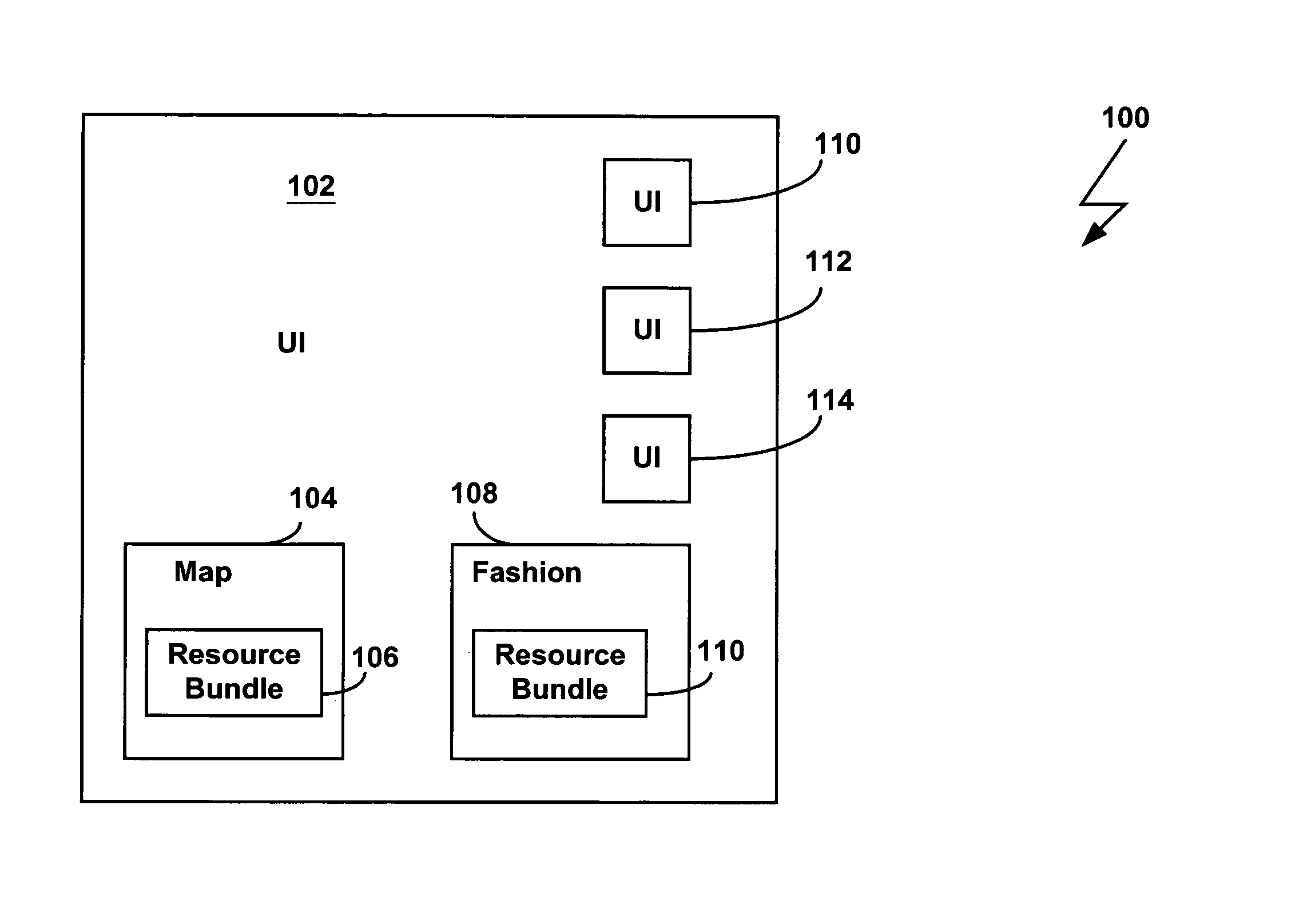
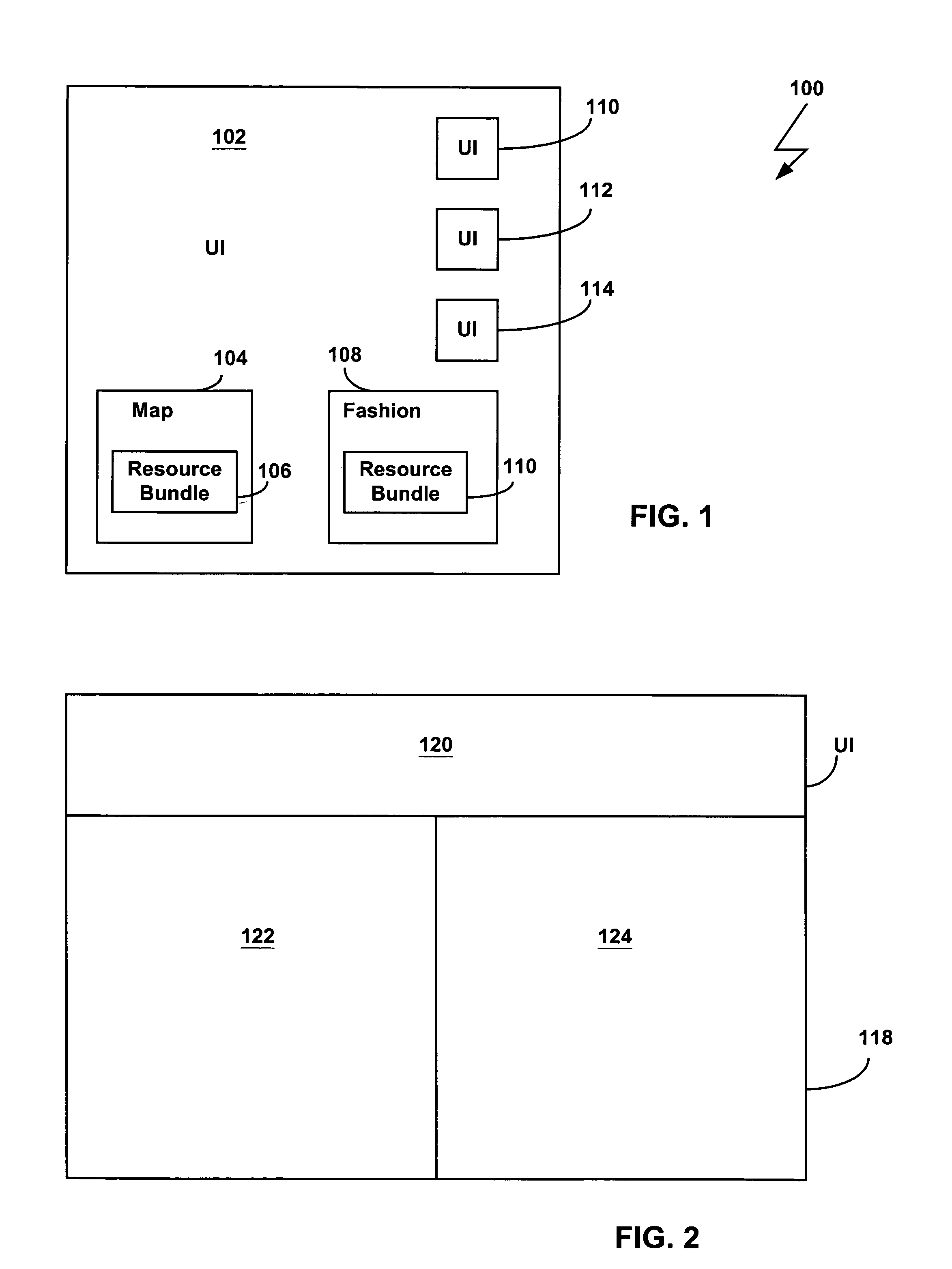
[0025]As shown in FIG. 1, a system 100 has a user interface (UI) object. The UI object 102 can have a graphical modality such as a two-dimensional or three-dimensional graphical user interface, or can have a different modality, such as a voice user interface commonly used in telephone response system.

[0026]The object 102 has a map component 104. The map component 104 contains instructions for handling and processing objects contained in the user interface. The map component 104 thus embodies logic associated with the user interface object 102. The map component 104 knows that certain UI resources are available to it and are defined in a resource bundle 106 with a list of UI objects and their characteristics. The resource bundle can be created by an application programmer or can be programmatically generated. The resource bundle contains, directly or by reference, the layout rule for each UI object and the requisite system call that displays and enable that UI object to generate an e...


PUM


Abstract

Methods and apparatus define a user interface for a computer program after execution of the computer program has begun. A user interface for the program is defined by: associating a map component and a fashion component on the fly at run time to generate the user interface; and executing the user interface with the associated function and appearance.

Description

BACKGROUND[0001]The invention relates to systems and methods of defining a user interface for computer program.[0002]Traditionally, graphical user interfaces have been employed to facilitate interaction of a user with software in a computer system. For example, typical objects in a GUI are icons presented on a background or “desktop”, with the icons representing a set of functions, application programs, system resources, or the like. These icons may be selected to instruct the computer to perform particular functions.[0003]GUI objects are generally created as part of a static application program construct that describes how a particular GUI object appears and what function is performed when that GUI is selected. Many visually-based application builder tools, such as Visual Basic, available from Microsoft Corporation of Redmond, Wash., have a graphical user interface that includes a “toolbox”, a “form window”, and a “property sheet,” among others. A toolbox typically contains icons t...

Claims


Application Information

Patent Timeline
IPC IPC(8): G06F9/44G06F3/00G06F3/048
CPCG06F8/38
Inventor CHANSLER, ROBERT J.
Owner ADOBE INC
Learn More