Pressure sensor

a technology of pressure sensor and pressure sensor, which is applied in the direction of fluid pressure measurement using elastically deformable gauges, instruments, and fluid pressure measurement by mechanical elements, can solve problems such as uneven pressure, and achieve the effect of preventing an uneven pressur

Inactive Publication Date: 2008-03-11
DENSO CORP
View PDF7 Cites 6 Cited by
  • Summary
  • Abstract
  • Description
  • Claims
  • Application Information

AI Technical Summary

Benefits of technology

[0012]In view of the above-described and other problems, the present invention provides a pressure sensor that structurally prevents an unevenness of an applied pressure on a pressure sensing portion.
[0013]The pressure sensor of the present invention includes a casing formed with a first case and a second case that has a pressure introduction hole for introducing a measurement object, a pressure sensing portion in the casing, and a metal diaphragm disposed between an end face of the first case and a reception face of the second case. The measurement object is introduced into a subspace that is formed as an expanded end of the pressure introduction hole in the second case for measurement of pressure by transmitting the pressure through the diaphragm to the pressure sensing portion, and the pressure sensing hole has an orifice that reduces a cross-sectional area of the pressure sensing hole. In this manner, the orifice in the pressure introduction hole reduces an inflow of the measurement object, or a liquid, thereby reducing a pressure of the liquid. As a result, the metal diaphragm on the pressure sensing portion is protected from a steep change of the pressure applied thereon. Therefore, the pressure is evenly applied on the pressure sensing portion.
[0014]Further, the evenness of the applied pressure prevents a crack or a breakage of the metal diaphragm and / or the snapping of an aluminum wire that couples the sensing portion to an outer circuit. In this case, the diameter of the orifice in the pressure sensor is preferably half the size of the diameter of the pressure introduction hole. The orifice of the above-specified size can reduce the applied pressure effectively, thereby enabling to achieve the effectiveness of the present invention.
[0015]Furthermore, the distance from the orifice to the metal diaphragm is preferably equal to or greater than 10 mm. In this manner, a fluid velocity of the measurement object is effectively reduced.
[0016]Furthermore, the subspace of the pressure introduction hole has a baffle structure for restraining movement of the measurement object toward the metal diaphragm. In this manner, the movement of the measurement object is restrained, and the applied pressure is evenly distributed on the sensing portion. The baffle structure is also effective for suppressing a reflected wave in the measurement object.
[0017]Furthermore, the baffle structure is one of a metal plate having plural holes, a metal net and a woolly metal material for achieving the above described effect.

Problems solved by technology

In addition, when the pressure transmits in a liquid, pressure wave is not easily attenuated, thereby causing a reflected pressure wave that also causes unevenness of the pressure.

Method used


Image

  • Pressure sensor
  • Pressure sensor
  • Pressure sensor

Examples


Embodiment Construction

[0024]Embodiments of the present invention are described with reference to the drawings. Like parts have like numbers in each of the embodiments.

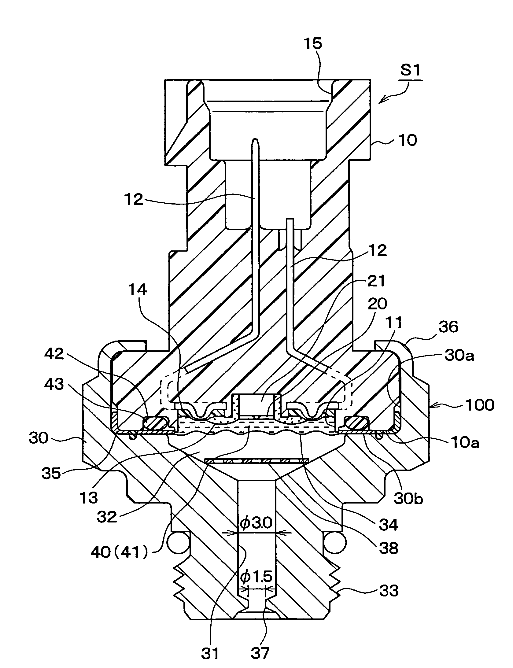
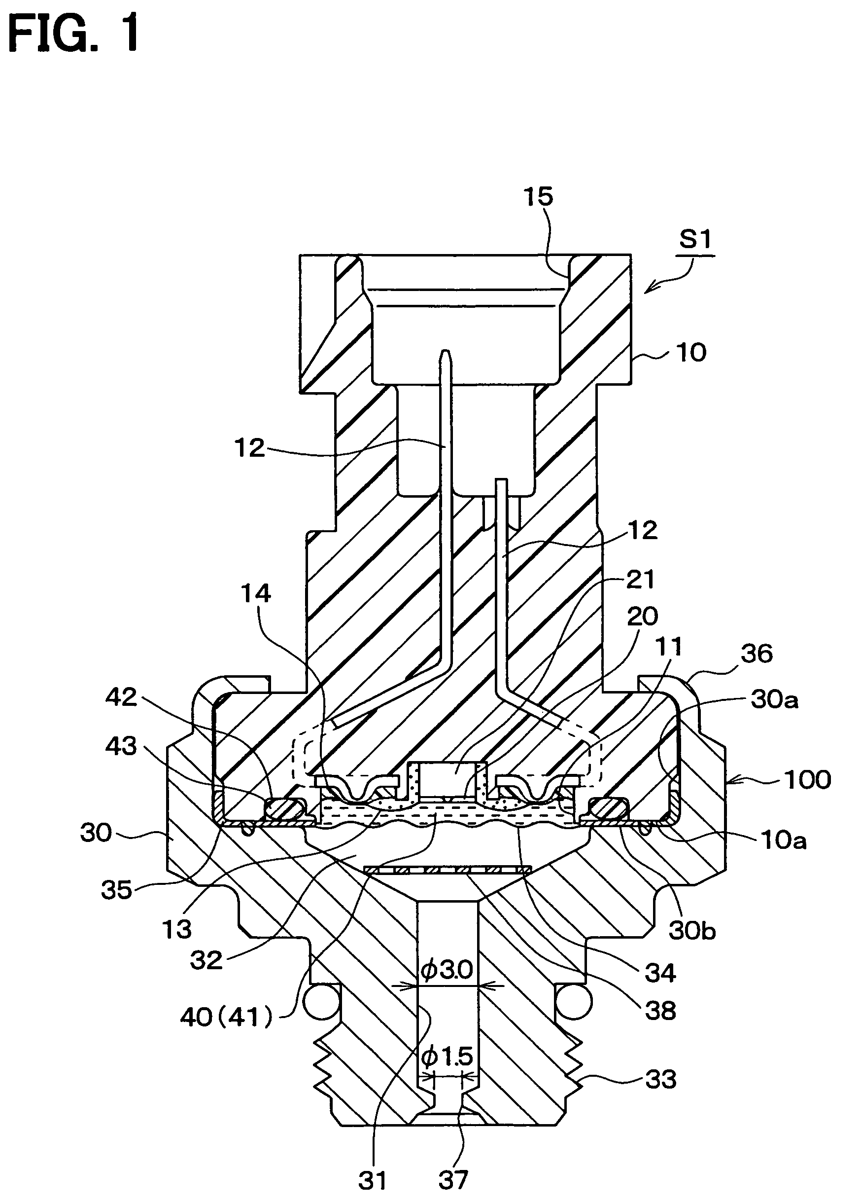
[0025]A pressure sensor in an embodiment of the present invention is described in the following. FIG. 1 shows a cross-sectional view of the pressure sensor S1. The pressure sensor S1 is used for, for example, detecting a pressure of a coolant in an air-conditioner on a vehicle, a differential pressure of a DPF filter in a diesel engine or similar purposes.

[0026]As shown in FIG. 1, a connector case 10 as a first case is formed by using resin such as PPS (Polyphenylene sulfide), PBT (Polybutylene terephthalate) or the like. The connector case 10 is substantially in a columnar shape in the present embodiment. The connector case 10 has a concave portion 11 on one end (a lower side in FIG. 1). The concave portion 11 has a sensor element 20 on a bottom surface.

[0027]The sensor element 20 has a diaphragm on its surface for detecting a pressure, an...


PUM

PropertyMeasurementUnit
distanceaaaaaaaaaa
pressureaaaaaaaaaa
diameteraaaaaaaaaa

Abstract

A pressure sensor includes a casing formed with a first case and a second case that has a pressure introduction hole for introducing a measurement object, a pressure sensing portion in the casing and a metal diaphragm disposed between an end face of the first case and a reception face of the second case. The measurement object is introduced into a subspace that is formed as an expanded end of the pressure introduction hole in the second case for measurement of pressure by transmitting the pressure through the diaphragm to the pressure sensing portion, and the pressure sensing hole has an orifice that reduces a cross-sectional area of the pressure sensing hole.

Description

CROSS REFERENCE TO RELATED APPLICATION[0001]This application is based on and claims the benefit of priority of Japanese Patent Application No. 2005-316415 filed on Oct. 31, 2005, the disclosure of which is incorporated herein by reference.FIELD OF THE INVENTION[0002]The present invention generally relates to a pressure sensor that detects a pressure of an object being introduced into the pressure sensor from a pressure introduction port.BACKGROUND OF THE INVENTION[0003]Conventionally, various types of pressure sensors are proposed for detecting a pressure that is introduced to a sensing portion of the sensor from a pressure introduction port. For example, U.S. Pat. No. 5,595,939 discloses a pressure sensor for detecting a pressure of an object. FIG. 4 shows a cross-sectional view of the pressure sensor in the disclosure.[0004]The pressure sensor shown in FIG. 4 is a diaphragm type pressure sensor that has a first case J1 and a second case (i.e., a housing J2) for respectively housin...

Claims


Application Information

Patent Timeline
Patent Type & Authority Patents(United States)
IPC IPC(8): G01L9/16
CPCG01L19/0038G01L19/0609G01L19/0645G01L19/143
Inventor SATO, JUNICHI
Owner DENSO CORP
Why Eureka
Try Eureka