Eureka AIR delivers breakthrough ideas for toughest innovation challenges, trusted by R&D personnel around the world.

Passive motion machine providing controlled body motions for exercise and therapeutic purposes

a passive motion machine and body technology, applied in the field of passive motion devices, can solve the problems of many unsuitable devices for suffering people, and achieve the effect of reducing pain and speeding up recovery

Inactive Publication Date: 2008-03-11
SUNCEPTS INC +1
View PDF20 Cites 22 Cited by
  • Summary
  • Abstract
  • Description
  • Claims
  • Application Information

AI Technical Summary

Benefits of technology

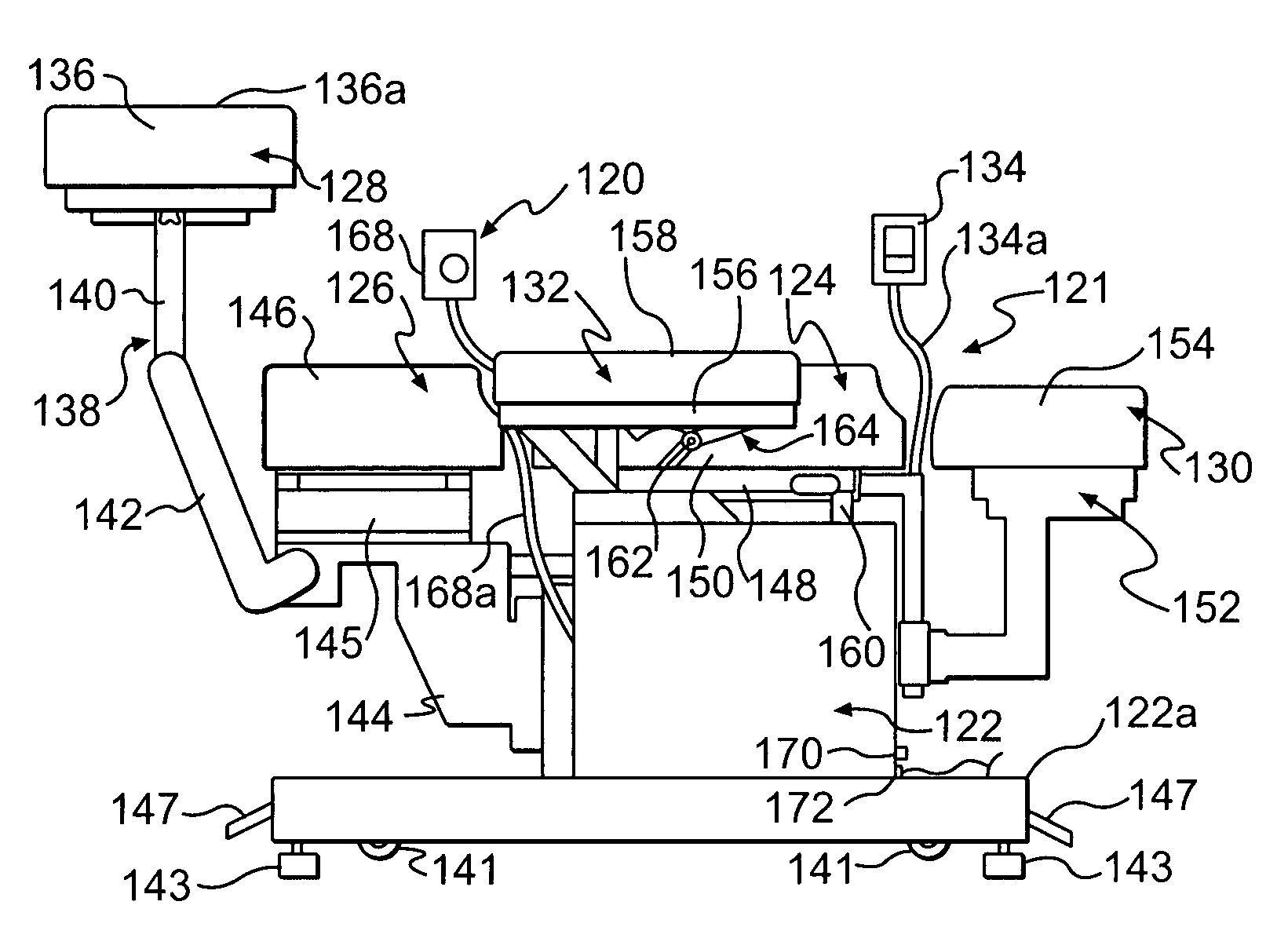
[0007]In accordance with the invention, a continuous passive motion apparatus or machine is provided which affords a number of important improvements or advantages over the prior art. As with U.S. Pat. No. 6,692,451, this invention is based, in part, on the appreciation that continuous passive motion can be beneficial in treating various muscular and skeletal injuries or disorders, and on the belief held by many health care professionals that the slow and passive movement of an injured joint or like disorder can reduce pain and / or speed the recovery of many patients with such disorders.
[0011]Preferably, the apparatus further comprises a calf support assembly connected to said main support assembly at one end of said main support assembly so as to support at least part of the legs of the user, said calf support assembly being connected to said main support assembly by an articulated connection for enabling said calf support assembly to be at least partially stowed away so as to enable a user to be positioned on said main support assembly without interference from said calf support assembly. Advantageously, the calf support assembly includes a support platform and the articulated connection is movable to a position wherein said platform is supported in a plane elevated with respect to the first-mentioned plane such that lower portions of the legs of the user are elevated with respect to the remainder of the body of the user and such that upper portions of the legs of the user extend at substantially right angles with respect to the lower portions of the legs and the trunk of the body of the user. Preferably, the articulated connection of said calf support assembly includes at least two pivotable links for enabling movement of said support platform into the first-mentioned plane and for enabling the spacing between said calf support assembly and said main support assembly to be varied.
[0022]Preferably, the apparatus further comprises a further elevated support member, movable with respect to said first support member and disposed, in one mode of use of the apparatus, at a common level with, and adjacent to, said first support member, for, in use, supporting at least a portion of the head of the user, said second support member being mounted for pivotable movement relative to said first support member, said motor means, when activated, selectively providing continuous cyclically repeated pivotable movement of said further support member about a vertical axis between spaced end positions so as to provide continuous passive bending motion of the cervical region of the body of the user.
[0049]In an important implementation, the handheld computer further enables setting of a time period for said pivoting movement and for said rotational movement.

Problems solved by technology

However, many of these devices are unsuitable for persons suffering from serious back pain because use thereof tends to increase the pain and / or because there is danger of injury (or further injury) to the back, e.g., to the spine or to the supporting muscles.

Method used


Image

  • Passive motion machine providing controlled body motions for exercise and therapeutic purposes
  • Passive motion machine providing controlled body motions for exercise and therapeutic purposes
  • Passive motion machine providing controlled body motions for exercise and therapeutic purposes

Examples


Embodiment Construction

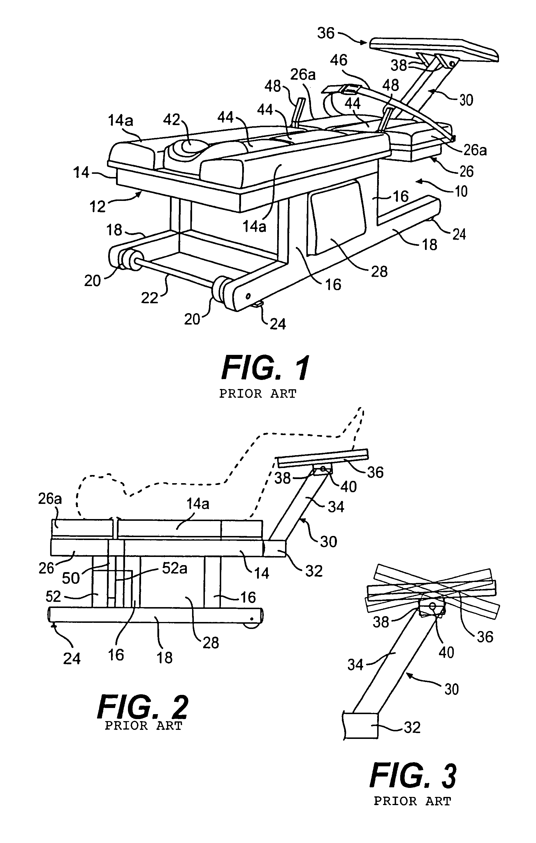
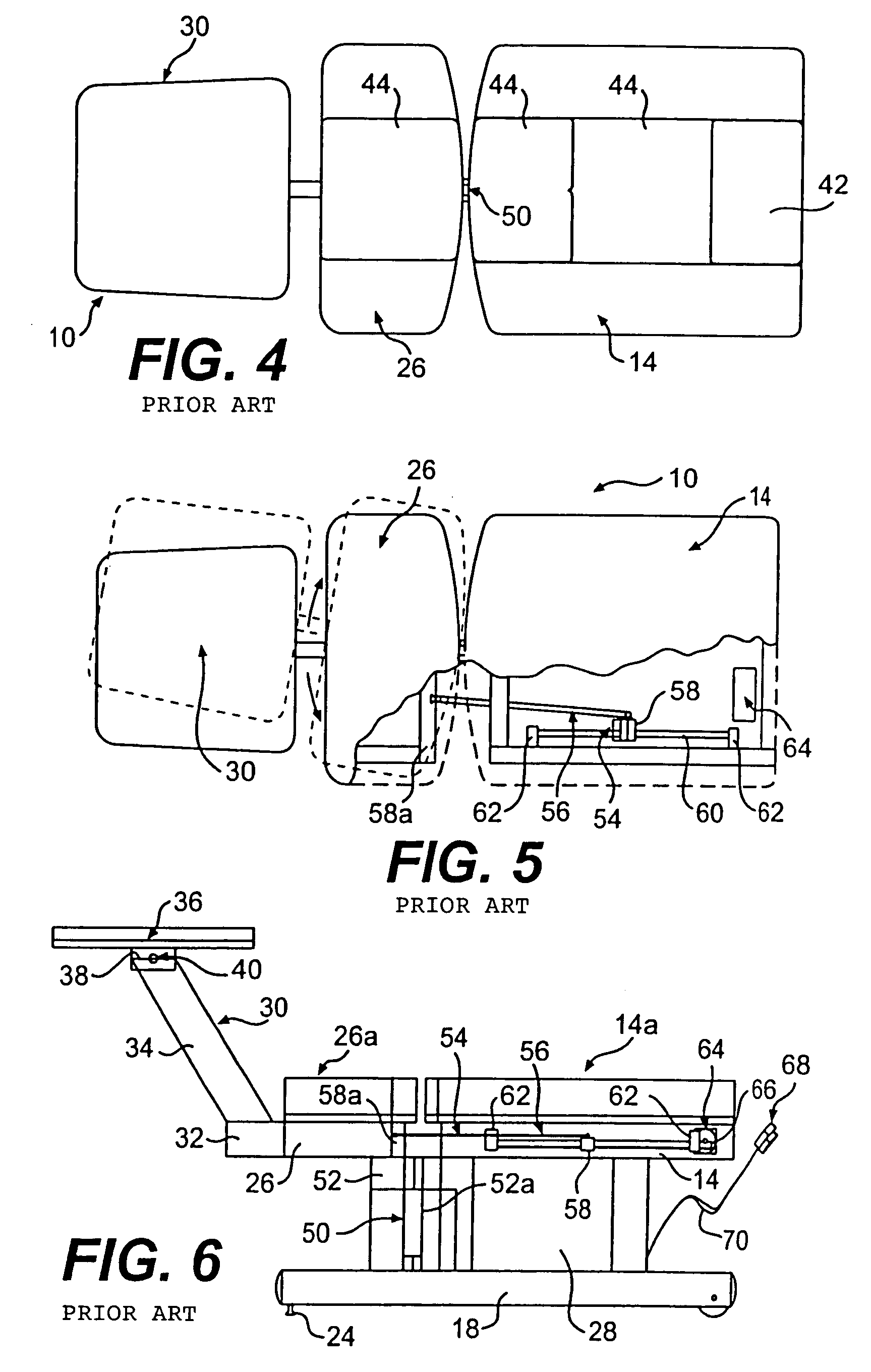
[0091]Referring to FIGS. 1 to 6, there is shown a preferred embodiment of the continuous passive motion and traction device as disclosed in U.S. Pat. No. 6,692,451. As indicated in FIG. 1, the device or machine, which is generally denoted 10, includes a frame 12 including an upper main table member 14 supported by legs 16 or like supports in a sled configuration formed by parallel support members 18. Wheels 20 mounted on a transverse axle 22 extending between the front ends of support members 18 enable the device 10 to be moved. Downwardly depending, adjustable leveling elements or levelers 24 located at the ends of support members 18 help fix the device 10 in place as well as to level the device. Levelers 24 are provided at both ends of support members 18 in FIG. 1 and at only one end in FIG. 2 and either option can be used.

[0092]In the configuration shown in FIG. 1, the overall support portion of device 10 includes the aforementioned main table member 14 and a further auxiliary, u...


PUM


Abstract

A passive motion exercise and / or treatment apparatus is provided which includes a main support assembly for supporting at least the head and torso of a user. The main assembly includes three support members which, in one mode of operation, are disposed in a common plane. The second and third members are movably connected to the first member, which is a backrest support member, and are movable relative thereto so as to respectively provide passive movement of both the head and, and the lumbar region, of a user. Cervical side bending and rotational movements and lumbar side bending and rotational movements can all be provided. A separable leg support assembly is adjustable to support the calves of the user in a plane elevated with respect to the common plane while the apparatus provides the aforementioned passive body movements.

Description

FIELD OF THE INVENTION[0001]The present invention relates to exercise and therapeutic devices and, more particularly, to passive motion devices, i.e., devices which put a passive user through prescribed movements without effort on the part of the user.BACKGROUND OF THE INVENTION[0002]It is estimated that in the United States alone, as of the mid-1990s, there were 25,000,000 people a day who suffered from some kind of back pain and that as many as nine out of ten Americans will suffer back pain at some time in their lives. The resultant total economic burden on industry in the United States is estimated at $40 to $50 billion annually.[0003]One approach to relieving back pain and cervical pain is through exercise or therapeutic movement, and a substantial number of exercise devices and machines have been developed for exercising the back. However, many of these devices are unsuitable for persons suffering from serious back pain because use thereof tends to increase the pain and / or bec...

Claims


Application Information

Patent Timeline
Patent Type & Authority Patents(United States)
IPC IPC(8): A61H1/00A61F5/00A61H1/02A61H5/00
CPCA61H1/001A61H1/0237A61H1/0292A61H2203/045A61H2203/0456A61H2201/0157A61H2201/1604A61H2201/1623A61H2201/1628A61H2201/164
Inventor SPLANE, JR., ROBSON L.SANTARSIERO, JR., JOHN R.
Owner SUNCEPTS INC
Why Eureka
Eureka Blog
Learn More