Nodular cast iron pipe die

A technology for ductile iron pipes and cast iron pipes, which is applied in the field of ductile iron pipe molds, can solve the problems of reduced rotational speed, reduced centrifugal force, and inability to ensure the normal formation of pipe bodies, and achieve the effect of recovering rotational speed and centrifugal force

Inactive Publication Date: 2022-03-08
倪善存
View PDF0 Cites 2 Cited by
  • Summary
  • Abstract
  • Description
  • Claims
  • Application Information

AI Technical Summary

Problems solved by technology

[0002] The essence of cast iron steel pipe is nodular cast iron pipe. Because nodular cast iron pipe has the essence of iron and the performance of steel, it is called this way. During the production and manufacturing process, magnesium is mainly added to molten iron, and then it is passed through the molten iron conduction equipment. It is imported into the cast iron pipe mold, and the cast iron pipe mold rotates under the driving device, relying on centrifugal force to make the imported molten iron diffuse and form; generally, the ductile iron pipe mold is driven by driving components such as a driving motor to rotate, and the general driving motor itself The rotating speed depends on the electric power supply and its internal rotating speed auxiliary components. Since the production process of the ductile iron pipe mold depends on the centrifugal force, once the driving motor of the existing ductile iron pipe mold decreases in speed, it will produce The centrifugal force is reduced, so that the normal formation of the pipe body cannot be ensured, and the existing pipe mold cannot prevent the speed from decreasing, and cannot repair the situation of the speed reduction in time

Method used


Image

  • Nodular cast iron pipe die
  • Nodular cast iron pipe die
  • Nodular cast iron pipe die

Examples


Embodiment Construction

[0024] The following will clearly and completely describe the technical solutions in the embodiments of the present invention with reference to the accompanying drawings in the embodiments of the present invention. Obviously, the described embodiments are only some, not all, embodiments of the present invention. Based on the embodiments of the present invention, all other embodiments obtained by persons of ordinary skill in the art without making creative efforts belong to the protection scope of the present invention.

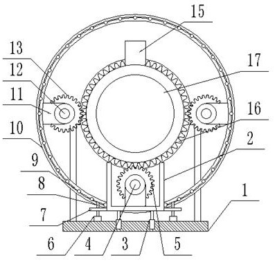
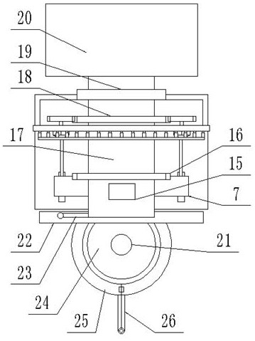
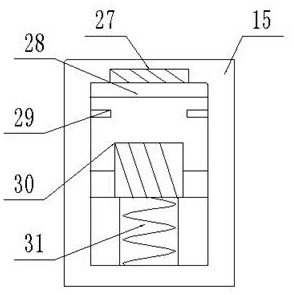
[0025] see Figure 1-7 , the present invention provides a technical solution: a ductile iron pipe mold, comprising: a support base 1, a first annular guide rail 19 and a cast iron pipe mold 17; the first annular guide rail 19 is vertically fixedly connected to the support base 1, and the cast iron pipe The mold 17 is horizontally inserted into the first circular guide rail 19, and the rear end of the cast iron pipe mold 17 is connected to the first circular gu...


PUM


Abstract

The invention discloses a nodular cast iron pipe die which comprises a supporting base, a first annular guide rail and a cast iron pipe die body. The first annular guide rail is connected to the supporting base, the cast iron pipe die is horizontally inserted into the first annular guide rail in a penetrating mode, and the rear end of the cast iron pipe die is rotationally connected into the first annular guide rail. A rotating speed reduction preventing mechanism is connected between the cast iron pipe die and the supporting base. When the rotating speed of the cast iron pipe die driven by the main driving motor is reduced, the centrifugal force is reduced, so that the main magnet block slides back under the action of resilience force of the first connecting spring, the adsorbed iron sliding block is pulled to be separated from the auxiliary magnet block and extruded to the pressure sensing switch, then the position of the auxiliary driving motor is fixed, and after the auxiliary driving motor is started, the pressure sensing switch is pressed to the pressure sensing switch. The auxiliary driving gear drives the cast iron pipe die to continuously rotate at a certain rotating speed, rotating speed recovery and centrifugal force recovery are achieved, and cast iron pipe manufacturing can be continuously carried out conveniently.

Description

technical field [0001] The invention relates to the technical field of ductile iron pipe molds, in particular to a ductile iron pipe mold. Background technique [0002] The essence of cast iron steel pipe is nodular cast iron pipe. Because nodular cast iron pipe has the essence of iron and the performance of steel, it is called this way. During the production and manufacturing process, magnesium is mainly added to molten iron, and then it is passed through the molten iron conduction equipment. It is imported into the cast iron pipe mold, and the cast iron pipe mold rotates under the driving device, relying on centrifugal force to make the imported molten iron diffuse and form; generally, the ductile iron pipe mold is driven by driving components such as a driving motor to rotate, and the general driving motor itself The rotating speed depends on the electric power supply and its internal rotating speed auxiliary components. Since the production process of the ductile iron pi...

Claims


Application Information

Patent Timeline
Patent Type & Authority Applications(China)
IPC IPC(8): B22D13/10B22D13/12B22D13/02
CPCB22D13/10B22D13/108B22D13/12B22D13/023
Inventor 倪善存
Owner 倪善存
Why Eureka
Try Eureka