Hydraulic shaft sealing arrangement for high-temperature applications

a technology of hydraulic shaft and sealing arrangement, which is applied in the direction of engine sealing, climate sustainability, sustainable transportation, etc., can solve the problems of affecting the performance of the aircraft engine, the lubricant of the two shaft bearings, and the oil used, so as to reduce the hazard of coking, improve the continuity of exchange of the entire sealing medium, and minimize the temperature of the sealing medium. , the effect of reducing the temperatur

Active Publication Date: 2008-03-18
ROLLS ROYCE DEUT LTD & CO KG
View PDF8 Cites 11 Cited by
  • Summary
  • Abstract
  • Description
  • Claims
  • Application Information

AI Technical Summary

Benefits of technology

[0006]A broad aspect of the present invention is to provide a hydraulic shaft sealing arrangement which prevents oil carbon formation in the high-temperature area, ensures reliability of sealing at all times, saves space, weight and assembly time and ensures rapid oil exchange.
[0008]The underlying idea of the present invention is a heat protection ring arranged before the annulus containing the sealing medium and at a certain distance from the annulus side faces adjacent to the high-pressure or high-temperature area, this heat protection ring being arranged on the one shaft and ending short of the other shaft while forming a narrow sealing gap. Thus, the annulus with the sealing medium is separated from immediate thermal influence in the high-temperature area by a heat shield and a thermally insulating air chamber / stagnation zone. The heating of the sealing medium and its tendency to coking as a result of the high temperatures and deposition of oil carbon particles at the particularly hot inner wall surfaces of the annulus are considerably reduced. The reduced formation of oil carbon improves the continuity of exchange of the entire sealing medium in the annulus, further minimizing the temperature of the sealing medium and the hazard of coking.
[0009]According to another important feature of the present invention, means are provided on the inner walls of the annulus which exert a pumping action on the sealing medium as the annulus rotates and accelerate the transport of the medium through the annulus, i.e. improve the continuous exchange of the sealing medium, thus further reducing its temperature. In particular the combination of measures for thermal protection and improved medium transport or exchange enables the temperature of the sealing medium to be lowered to a level that ensures, in the high-temperature area, perfect sealing of the high-pressure shaft against the low-pressure shaft or the rear bearing chamber adjacent to the high-pressure area and, thus, protection of the respective rolling bearings and the carbon mating ring seal as well as reliable operation of the gas turbine. Furthermore, active cooling of the carbon mating seal ring running face enhances the service life of the carbon mating ring seal used.
[0010]According to a further significant feature of the present invention, the annulus for the sealing medium provided on the outer rotating shaft is formed by a first annular disk formed on the shaft and a separate, second annular disk. This facilitates assembly of the shaft and reduces the size and weight in this area. An angular ring is inserted in the annulus in such a manner that the sealing medium near the first, most severely heated annular disk and near the bottom can flow off through an annular duct formed between the bottom and the second annular disk via the inward, free edge of the second annular disk into the bearing chamber. Thus, the hottest, most readily coking sealing medium will be scavenged first, actually such that sealing medium will always be present in the annulus at a level given by the height of the second annular disk, even if the supply of oil is interrupted, and the sealing function is maintained.

Problems solved by technology

In high-temperature applications, specifically the sealing of the bearing chamber for the high-pressure shaft and the low-pressure shaft of a gas turbine engine against the compressor air supplied at a temperature of 400° C., for example, these hydraulic sealing arrangements are problematic in that the oil, which is used as sealing medium and lubricant of the two shaft bearings, is liable to degradation and coking as a result of the high temperatures.
The considerable overall size and high weight of this design result in the known disadvantages for an aircraft engine.
Removal of the sealing medium from an annulus area formed into the bottom is, however, disadvantageous in that sealing against the hot high-pressure zone will be affected if the supply of oil and, thus, the amount of sealing medium in the annulus is inadequate.

Method used


Image

  • Hydraulic shaft sealing arrangement for high-temperature applications
  • Hydraulic shaft sealing arrangement for high-temperature applications

Examples


Embodiment Construction

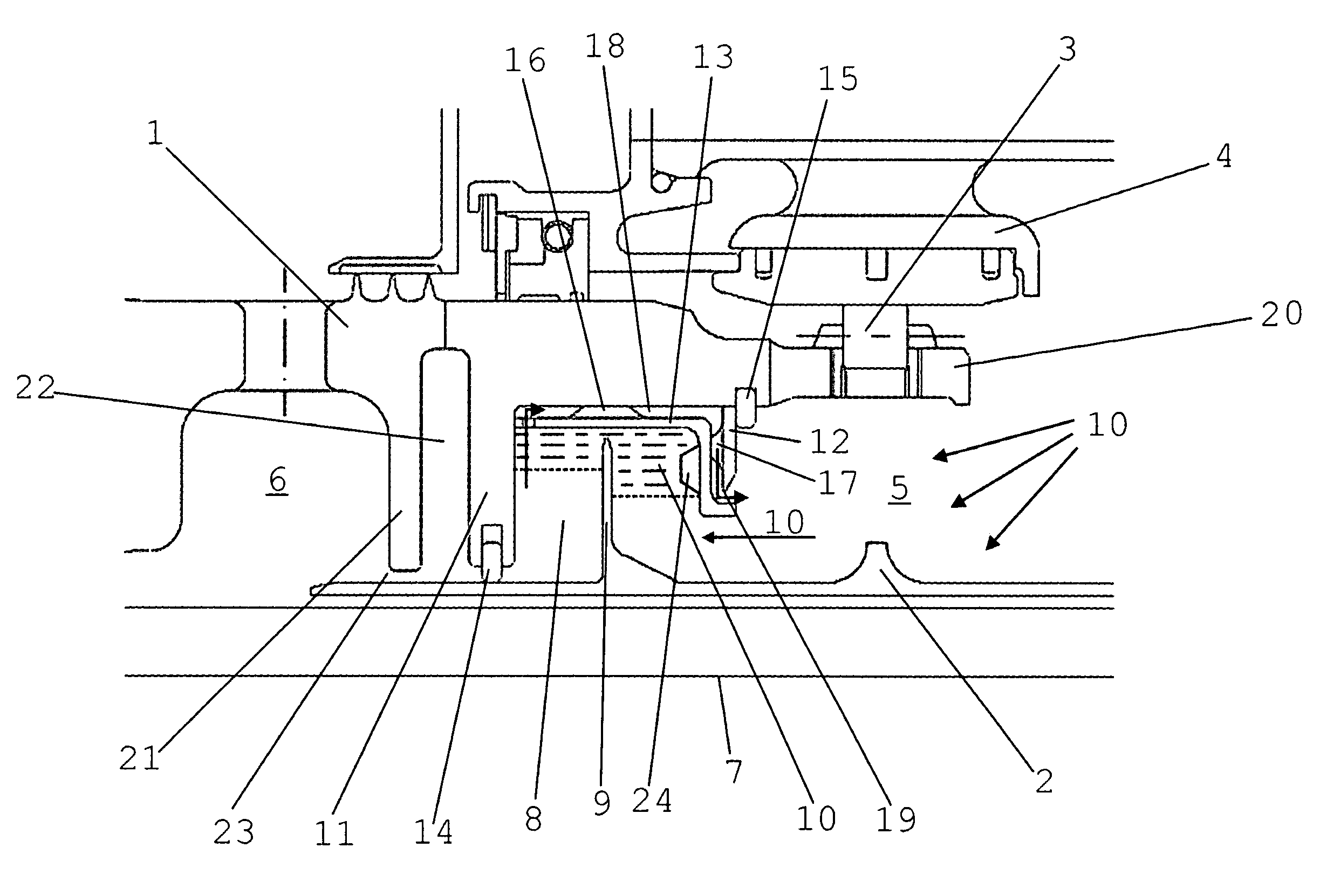
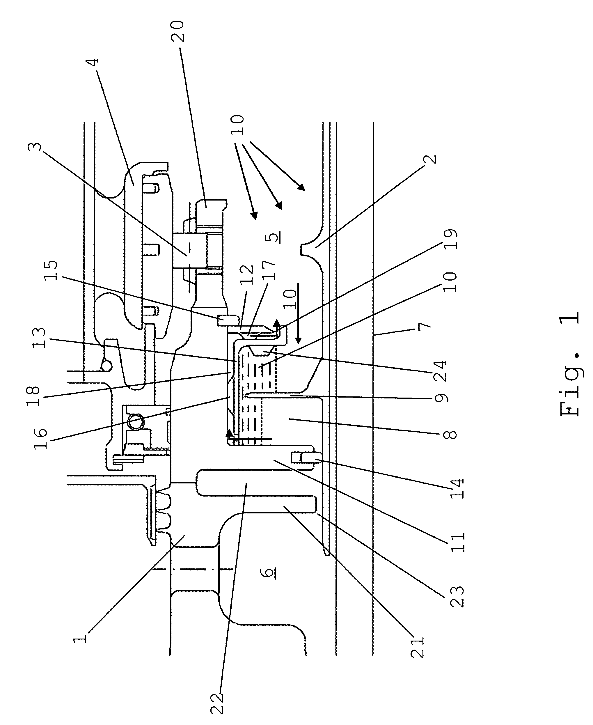
[0013]The high-pressure shaft 1 and the low-pressure shaft 2 of a gas turbine engine are concentrically supported in the turbine casing 4 by means of a first rolling bearing 3 for the high-pressure shaft 1 and a second rolling bearing (not shown) for the low-pressure shaft 2. For cooling and lubrication, the bearing chamber 5 so formed is continuously supplied with coolant-lubricant (oil). In order to seal the low-pressure zone in the bearing chamber 5 against the relatively hot high-pressure zone 6 to avoid coking and ignition of the oil, the two, preferably co-rotating shafts, here the high-pressure shaft 1 and the low-pressure shaft 2, are sealed against each other by means of a hydraulic sealing arrangement. The hydraulic sealing arrangement comprises an U-shaped annulus 8 provided on the high-pressure shaft 1 and open to the rotational axis 7 which, as a result of the centrifugal forces effected by the rotation of the high-pressure shaft 1, is filled with coolant-lubricant supp...


PUM


Abstract

On a hydraulic shaft sealing arrangement for high-temperature applications, a heat protection ring (21) and an air chamber (22) are arranged before the annulus (8) containing the sealing medium (10) for thermal insulation, while spacers (16, 17) for the generation of a pumping action are provided in the annulus continuously supplied with fresh sealing medium (oil) to accelerate liquid transport. The hazard of coking and oil carbon deposition is thereby minimized. A split design of the annulus with an inserted annular ring also provides for an improved hydraulic shaft sealing arrangement optimized for weight, overall height, manufacture and assembly time.

Description

[0001]This application claims priority to German Patent Application DE 10 2004 040 242.6 filed Aug. 13, 2004, the entirety of which is incorporated by reference herein.BACKGROUND OF THE INVENTION[0002]This invention relates to a hydraulic shaft sealing arrangement for high-temperature applications, more particularly for concentric shafts of a gas turbine engine, to seal the high-pressure shaft bearing chamber located in the low-pressure zone and the low-pressure shaft against the high-pressure zone.[0003]Hydraulic sealing arrangements, as is generally known, are used for contact-free sealing between two concentric, co-rotating shafts. In principle, such sealing arrangements can also be used with only one rotating shaft. The sealing arrangement normally consists of an essentially U-shaped annulus arranged on the inner circumference of the outer shaft which is filled with a fluidic sealing medium, preferably oil, supplied from the lubricating circuit of the respective engine by the ef...

Claims


Application Information

Patent Timeline
Patent Type & Authority Patents(United States)
IPC IPC(8): F16J15/40
CPCF01D11/04F01D25/183F16J15/42Y02T50/671Y02T50/60
Inventor GAEBLER, MIKLOSHEIN, STEFAN
Owner ROLLS ROYCE DEUT LTD & CO KG
Why Eureka
Try Eureka