Light amount adjusting apparatus and projector using the same

a technology of light amount and adjustment apparatus, which is applied in the direction of projectors, instruments, camera diaphragms, etc., can solve the problems of difficulty in controlling a voltage in such a manner, affecting the brightness of the surrounding, and affecting the viewing

Inactive Publication Date: 2008-03-18
NISCA KK
View PDF8 Cites 32 Cited by
  • Summary
  • Abstract
  • Description
  • Claims
  • Application Information

AI Technical Summary

Benefits of technology

[0012]A second aspect is such a thing that, in the above-described first configuration, the restriction unit is configured by a stopper member which blocks a predetermined angle or more turn of the light amount adjusting plate, and the holding unit is configured by a biasing unit such as a spring and a magnet which bias the light amount adjusting plate to this stopper member, and by this means, it is possible to surely hold the light amount adjusting plate, and a mechanism for that purpose becomes simple.
[0023]A thirteenth aspect is such a thing that, in the above-described twelfth configuration, the light amount adjusting wings are supported so as to turn in a traveling direction of the light path on a pair of rotation supporting shafts which were allocated in nearly parallel to each other, at both side rims of the projection light path, and the drive rotation shaft is allocated in nearly parallel to the rotation supporting shaft, and it is configured so as to transmit rotation of the drive rotation shaft to the above-described each rotation supporting shaft, respectively, by a transmission member which was allocated in a direction which is nearly orthogonal to this drive rotation shaft, and by this means, it becomes possible to provide a small-size and compact projector.

Problems solved by technology

Its cause is, for example, that a person feels light is too bright when an image is made suddenly bright in such a state that pupils of a human, who uses it at a dark place, are opened, and, inversely, at a bright place, a human feels an image placed on a screen is too dark, and so on, and viewability due to brightness of a surrounding becomes a problem.
However, the liquid crystal panel has a special relation between a voltage and a transmission factor, and there were such problems that it is difficult to control a voltage in such a manner that red, blue and green change evenly on the occasion of changing brightness by changing a voltage, and in addition, a hue also changes on the occasion of adjustment of brightness.
Therefore, it brought about an undesirable result for miniaturization and space saving of an apparatus.
However, by adoption of the suchlike configuration, a next problem will newly occur.
In sum, as shown in FIG. 11, it is difficult to apply accurate light amount control to a pair of wing members which can be rotated (swung), in a projection light path, in a traveling direction of this light path, due to backlash of a opening and closing mechanism, and in particular, it becomes difficult to carry out light amount adjustment in such a state that the opening of the light path was widely opened. FIG. 11(a) is a state diagram in which the light path was fully opened, and FIG. 11(b) is a state diagram in which the light path was fully closed.

Method used


Image

  • Light amount adjusting apparatus and projector using the same
  • Light amount adjusting apparatus and projector using the same
  • Light amount adjusting apparatus and projector using the same

Examples


Embodiment Construction

[0037]Hereinafter, preferred embodiments of the invention will be described on the basis of the drawings.

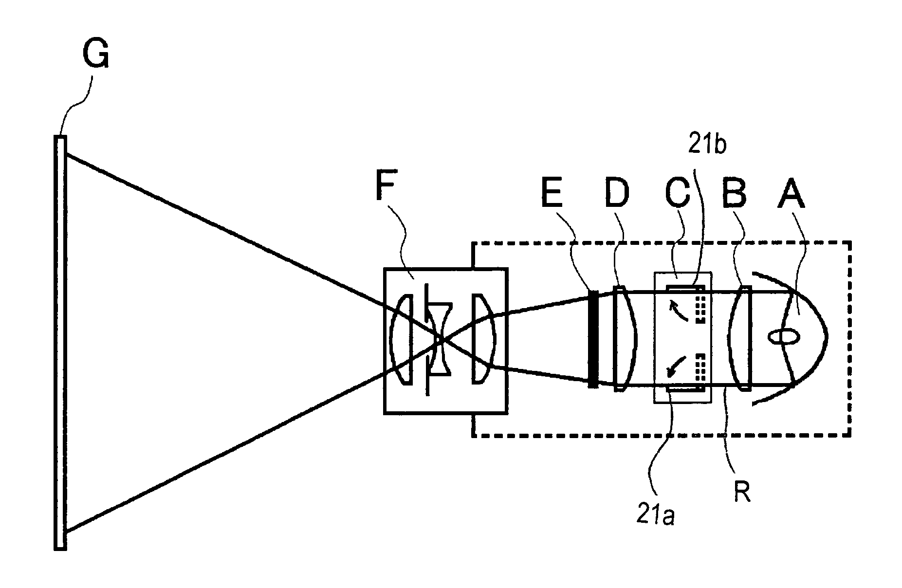
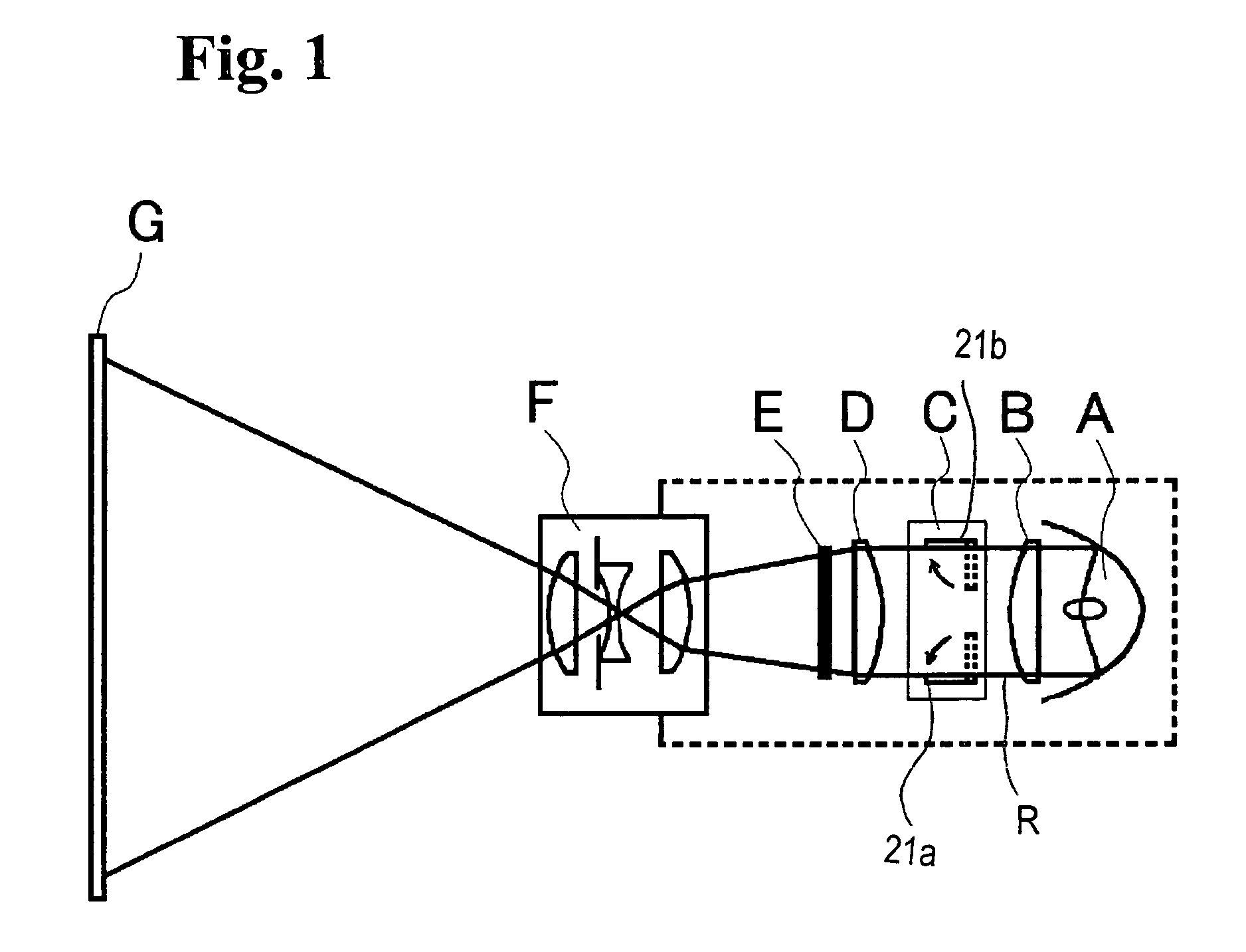
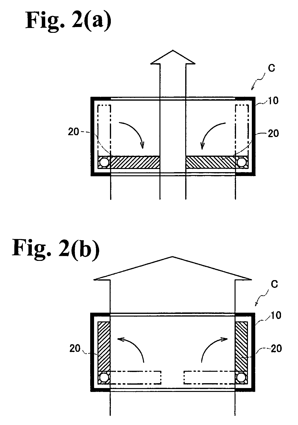
[0038]FIG. 1 is a schematic block diagram of a projector which used the invention, and FIGS. 2(a) and 2(b) are conceptual explanatory diagrams of light amount adjustment thereof, and FIG. 3 is an overall explanatory diagram of a light amount adjusting apparatus. In FIG. 1, a projector is configured by a light source A, a condenser lens B which converts light from this light source A into parallel light rays, an illumination optical system D including a dichroic mirror which color-luminosity separates light from this lens B, a liquid crystal panel E which receives light from this illumination optical system D, and a projection lens F which project light which passed through this liquid crystal panel E. Various methods are known for configuring this projection optical system, and a light source section (light source A etc.), an image forming section (liquid crystal panel E etc.) an...


PUM


Abstract

At least a pair of light amount adjusting plates is allocated at peripheral side rim portions of a light path through which light from a light source is projected. These light amount adjusting plates are drivable between a narrow-down position in which they enter into the light path and a retreat position in which they retreat to outside of the light path. A restriction member such as a stopper member restricts a rotation of the light amount adjusting plate at the retreat position, and a holding unit holds the light amount adjusting plate to this restriction member. The restriction member blocks a predetermined angle or further rotation of the light amount adjusting plate, and the holding unit, such as a spring or a magnet, biases the light amount adjusting plate to the restriction member.

Description

BACKGROUND OF THE INVENTION AND RELATED ART STATEMENT[0001]This invention relates to a light amount adjusting apparatus which adjusts a light amount on the occasion of projecting an image, which was formed by an image forming unit such as a liquid crystal panel, on a screen, by a projection lens, and a projector which used this.[0002]In general, an apparatus such as a liquid crystal projector, which projects alight image on a screen, is widely used as an apparatus which is connected to imaging devices such as a computer and a television receiver, and projects images which were outputted from these imaging devices, on a screen by a projection lens.[0003]There is such a case that someone feels a light image, which was projected by the suchlike projector, too bright, and dark, depending on a circumstance where it is used. Its cause is, for example, that a person feels light is too bright when an image is made suddenly bright in such a state that pupils of a human, who uses it at a dark...

Claims


Application Information

Patent Timeline
Patent Type & Authority Patents(United States)
IPC IPC(8): G03B21/14G02B5/00G03B9/06
CPCG02B5/005G03B9/06G03B21/14G03B21/2053
Inventor HARA, TOYOYUKINAKAJIMA, KATURAKUSUNOKI, TOKUROHAYAKAWA, YUKIHIKO
Owner NISCA KK
Why Eureka
Try Eureka