Collimator with variable focusing and direction of view for nuclear medicine imaging

a collimator and nuclear medicine technology, applied in the field of nuclear medicine, can solve the problems of special problems in collecting radiation emission and creating images, one-dimensional collimation or slat geometry used by slat detectors, and burdening slat detectors with other undesirable limitations, etc., and achieves the effect of improving the imaging of small organs and high resolution

Active Publication Date: 2008-03-18
SIEMENS MEDICAL SOLUTIONS USA INC
View PDF4 Cites 23 Cited by
  • Summary
  • Abstract
  • Description
  • Claims
  • Application Information

AI Technical Summary

Benefits of technology

[0012]The present invention solves the existing need by providing a new collimator geometry that enhances the imaging of small organs with high resolution or in an efficient manner. According to the present invention, a novel slat collimator for use in nuclear medicine imaging is provided. The slat collimator comprises a first layer comprising a plurality of spaced apart elongated slats and a second layer comprising a plurality of spaced apart elongated slats. The slats of the second layer are positioned orthogonally with respect to the slats of the first layer. The slats are constructed of a radiation attenuation material, such as tantalum, tungsten, lead and the like.

Problems solved by technology

While maintaining certain advantages, such as a better sensitivity-resolution compromise, over, e.g., traditional Anger cameras, slat detectors are burdened by some other undesirable limitations.
For example, the one dimensional collimation or slat geometry used by slat detectors complicates the image reconstruction process.
It is well known in the art that nuclear medicine imaging of small organs, such as brain, heart, kidneys, thyroid, and the like present special problems in collecting radiation emission and creating images from the collected data.

Method used


Image

  • Collimator with variable focusing and direction of view for nuclear medicine imaging
  • Collimator with variable focusing and direction of view for nuclear medicine imaging
  • Collimator with variable focusing and direction of view for nuclear medicine imaging

Examples


second embodiment

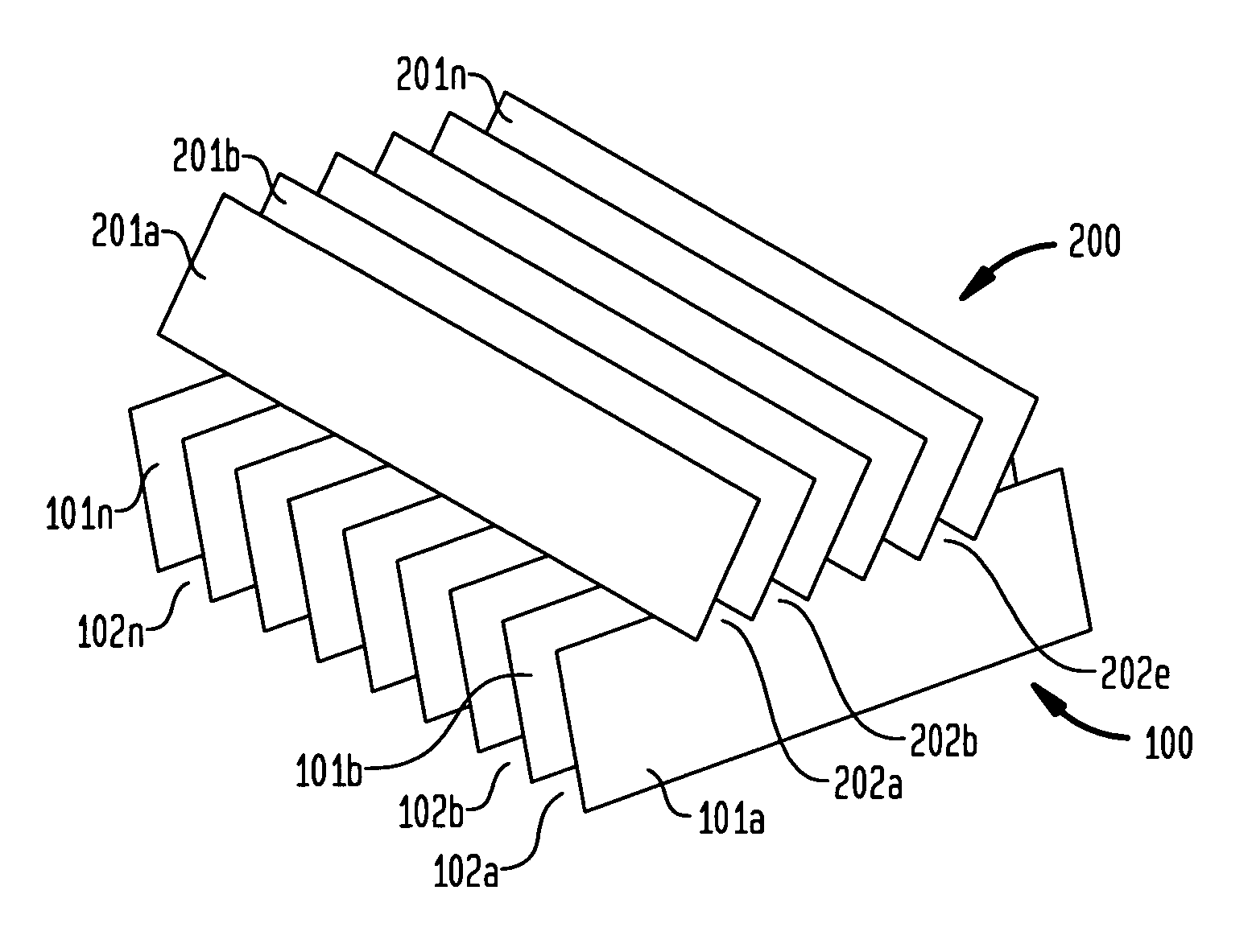
[0030]In a second embodiment the spaces (102a, 102b, . . . 102n) between the slats in the first layer (100) can be varied. Similarly, the spaces (202a, 202b, . . . 202n) between the slats in the second layer (200) can be varied. As used herein, variable spaces is intended to mean that the distance between the slats (101a, 101b, . . . 101n; 201a, 201b, . . . 201n) at one end of said slates is less than the distance between slats at the other end of said slats. By varying the spaces between the slats in this manner, non-parallel beam collimators are created. In addition, the direction of view can be changed using such a variable collimator. In order for direction of view to be changed in a general manner, a means creating repulsive forces between the slats needs to be created.

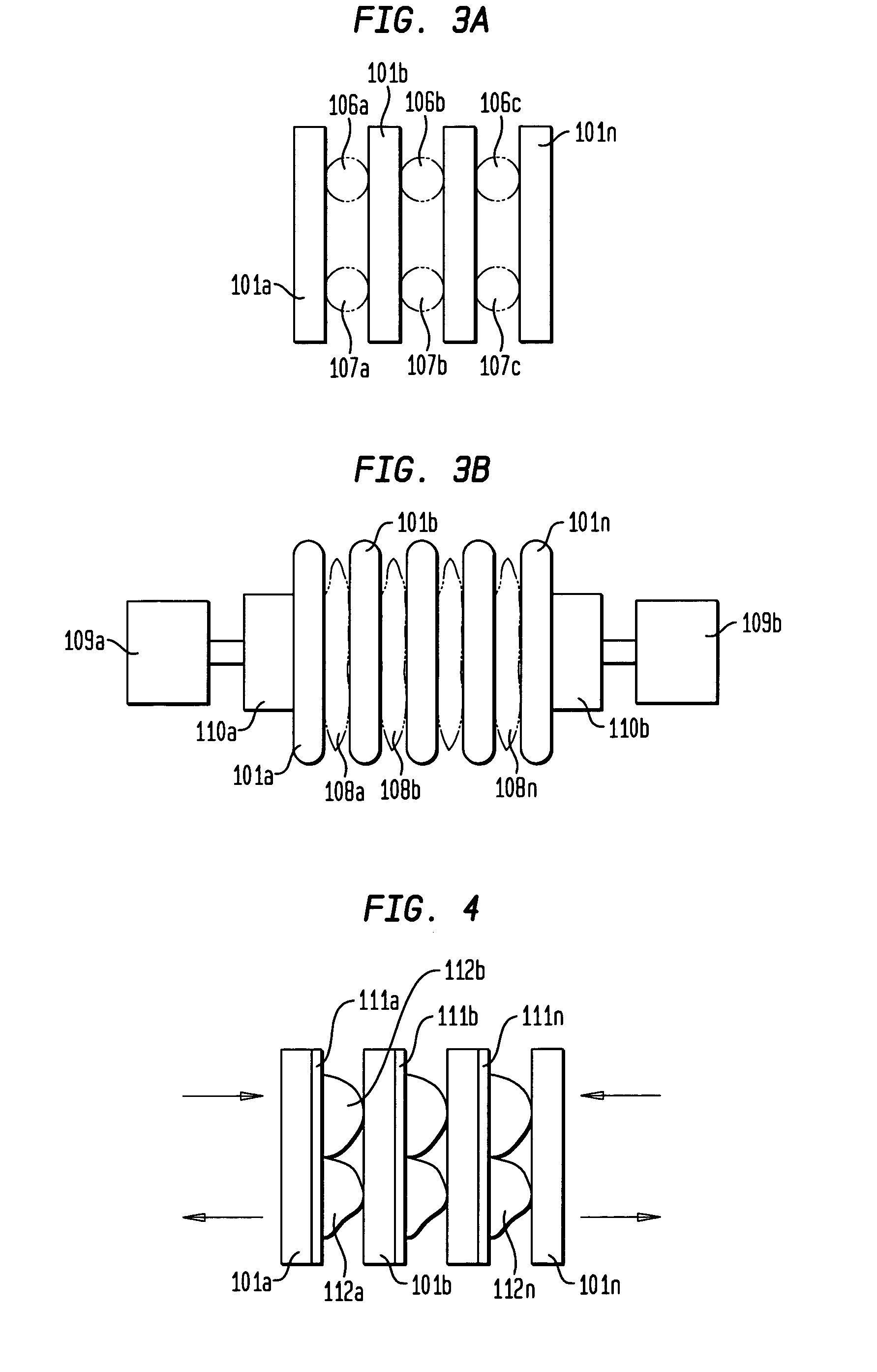
[0031]In one aspect of this embodiment, the slats (101a, 101b, . . . 101n; 201a, 201b, . . . 201n) can be held apart by springs. As shown in FIG. 3A, the slats (101a, 101b, . . . 101n) are held apart by springs (...

third embodiment

[0034]In a third embodiment, the spaces in one layer, e.g., spaces (102a, 102b, . . . 102n) between the slats in the first layer (100) are non-variable, i.e., fixed, such as described above. The spaces in a second layer, e.g. spaces (202a, 202b, . . . 202n) between the slats in the second layer (200) can be varied and under direct directional control, such as described above. Alternatively, the spaces (102a, 102b, . . . 102n) between the slats in the first layer (100) can be varied and under direct directional control. The spaces in a second layer, e.g. spaces (202a, 202b, . . . 202n) between the slats in the second layer (200) are non-variable, i.e., fixed.

[0035]By varying the spaces between the slats in this manner, non-parallel beam collimators are created. Such collimators may be advantageous in SPECT studies of small organs, such as brain, heart, kidney, thyroid, etc. The convergence of the collimator can be changed to adapt for each study. Also, the convergence can be changed ...


PUM


Abstract

According to the present invention, a novel slat collimator for use in nuclear medicine imaging is provided. The slat collimator comprises a first layer comprising a plurality of spaced apart elongated slats and a second layer comprising a plurality of spaced apart elongated slats. The slats of the second layer are positioned orthogonally with respect to the slats of the first layer. The slats are constructed of a radiation attenuation material and the spaces between the slats may be non-variable or variable.

Description

BACKGROUND OF THE INVENTION[0001]1. Field of the Invention[0002]The present invention generally relates to nuclear medicine, and systems for obtaining nuclear medical images of a patient's body organs of interest. In particular, the present invention relates to a novel collimator with variable focusing and direction of view for nuclear medicine imaging, particularly for single photon imaging including single photon emission computed tomography (SPECT).[0003]2. Description of the Background Art[0004]Nuclear medicine is a unique medical specialty wherein radiation is used to acquire images that show the function and anatomy of organs, bones or tissues of the body. Radio pharmaceuticals are introduced into the body, either by injection or ingestion, and are attracted to specific organs, bones or tissues of interest. Such radio pharmaceuticals produce gamma photon emissions that emanate from the body. One or more detectors are used to detect the emitted gamma photons, and the informatio...

Claims


Application Information

Patent Timeline
Patent Type & Authority Patents(United States)
IPC IPC(8): G21K1/02
CPCG21K1/025
Inventor HAWMAN, ERIC G.
Owner SIEMENS MEDICAL SOLUTIONS USA INC
Why Eureka
Try Eureka