
Linear power amplifier with multiple output power levels

a power amplifier and output power technology, applied in the direction of automatic tone/bandwidth control, tone control, gain control, etc., can solve the problems of power amplifiers that exhibit degraded power efficiency during, power amplifiers that provide somewhat non-linear amplification, and degrade the linearity of power amplifiers at very low quiescent current levels

Active Publication Date: 2008-03-18
QORVO US INC
View PDF18 Cites 30 Cited by
  • Summary
  • Abstract
  • Description
  • Claims
  • Application Information

AI Technical Summary

Benefits of technology

This patented design allows for two different types of amplification stages connected together by means other than just one type of amplifying element (a single-stage). These stages work independently from each other but they share some common features like inductors or capacitors used during operation. By adding these components at certain points along their way, this technology improves overall performance without sacrificing any specific characteristics needed for optimal functioning.

Problems solved by technology

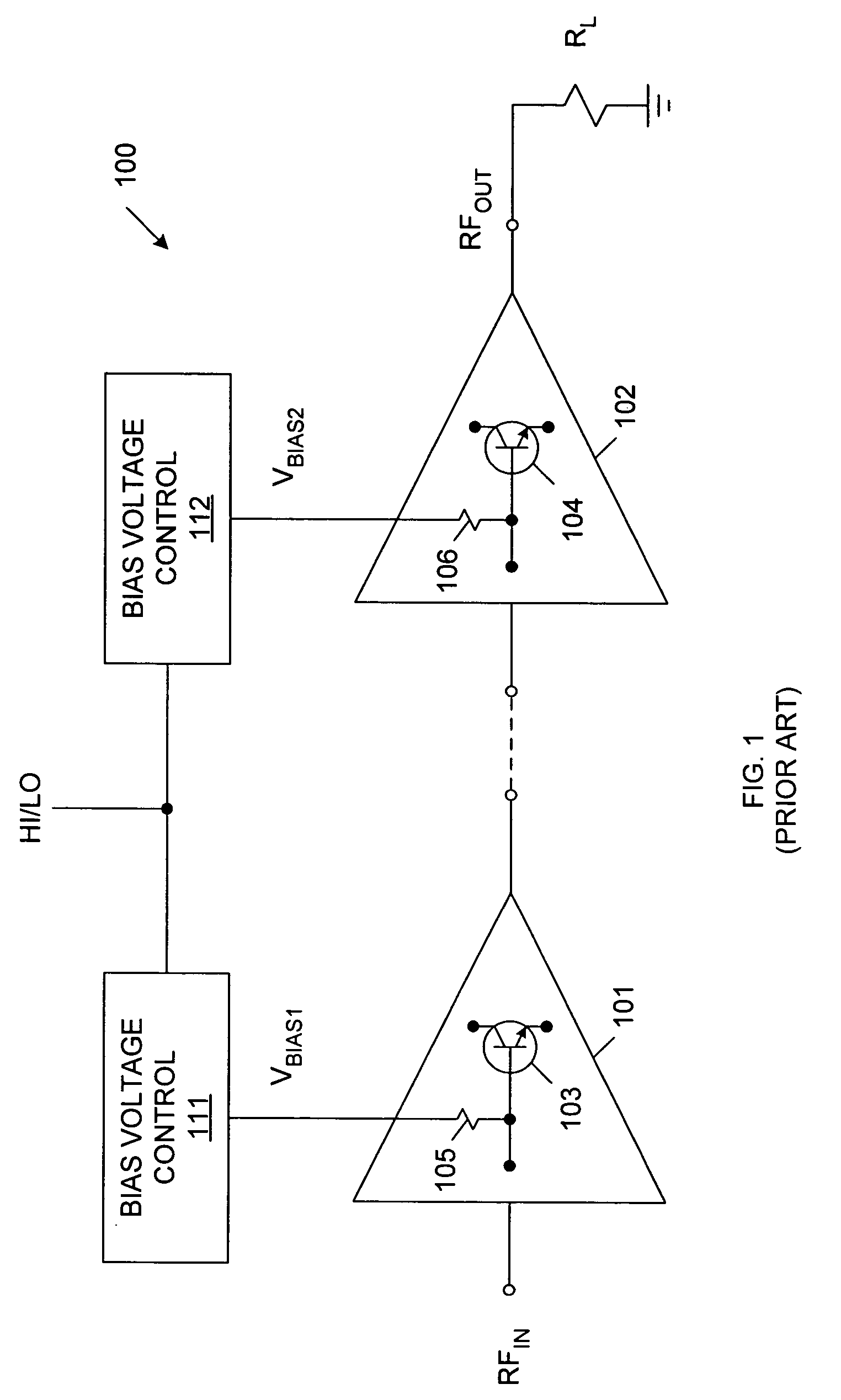
The technical problem addressed in this patent text is to create a power amplifier that does not require a low quiescent current density during low power operation, while also maintaining linear amplification and an optimized load impedance for both high power and low power operations.

Method used


Image

  • Linear power amplifier with multiple output power levels
  • Linear power amplifier with multiple output power levels
  • Linear power amplifier with multiple output power levels

Examples


Embodiment Construction

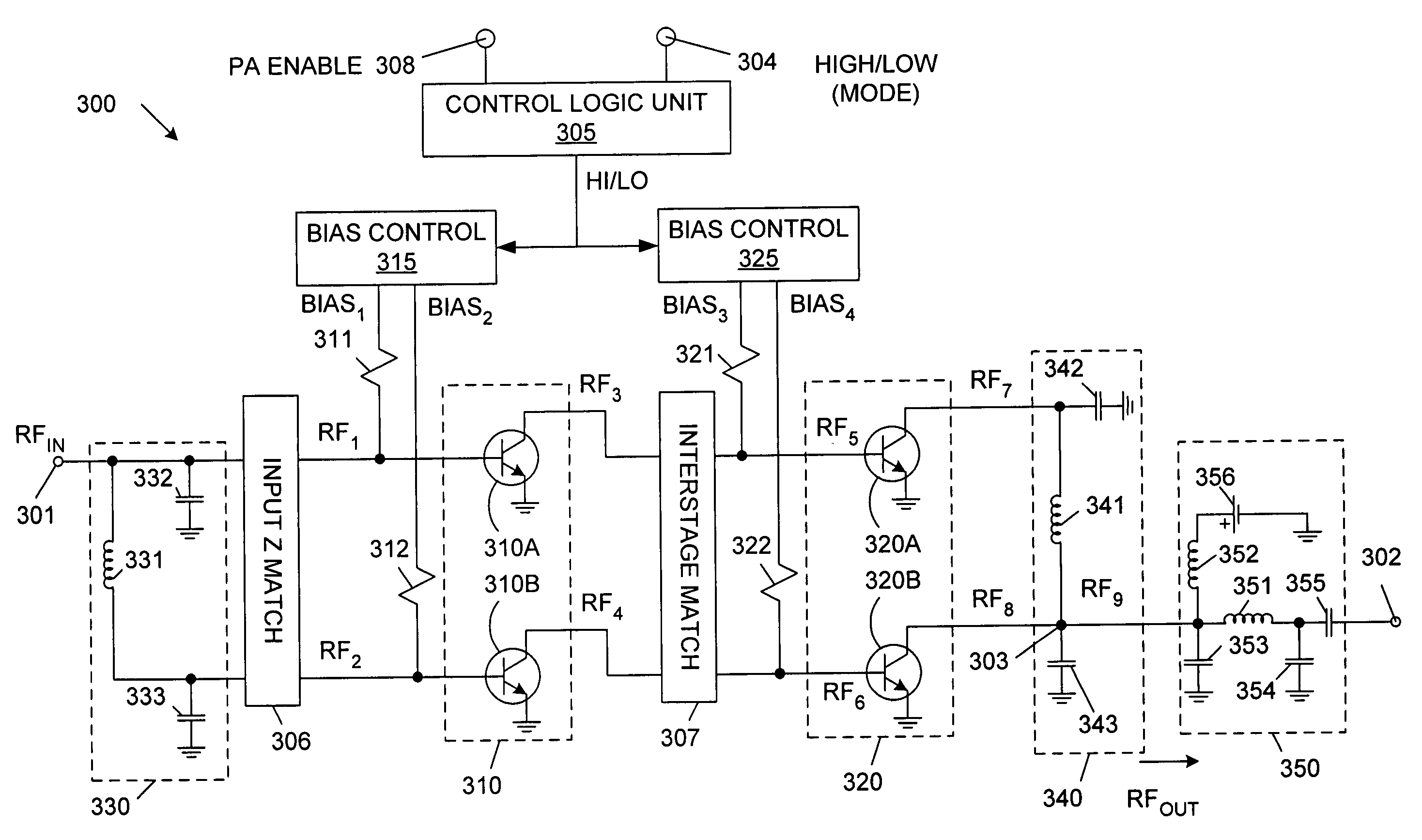
[0023]Skilled artisans will understand that certain well-known electronic circuit features (e.g., power supply lines) have been omitted so as to more clearly illustrate embodiments of the invention. Like-numbered elements in the drawings refer to the same or substantially similar elements among the various embodiments. For example, embodiments are generally described in terms of bipolar junction transistor (BJT) technology (e.g., multi-cell heterojunction bipolar junction transistors (HBTs)), but skilled artisans will understand that field effect transistor (FET) technology or even vacuum tube technology is easily adapted to the disclosed circuit topologies. For instance, an FET or vacuum triode may be substituted for a BJT.

[0024]Some embodiments are formed on a gallium arsenide (GaAs) substrate using conventional GaAs fabrication. Other semiconductor materials (e.g., silicon, indium phosphide) may be used in other embodiments.

[0025]Embodiments are described in terms of cellular rad...


PUM


Abstract

A power amplifier stage has a first amplifier subsection and a second amplifier subsection coupled in a parallel configuration. The first amplifier subsection receives a signal to be amplified and the second amplifier subsection receives the signal to be amplified via a first delay line. The amplified output signal of the first amplifier subsection is passed through a second impedance inverter and is combined with the amplified output signal from the second amplifier subsection. In a low power mode, the first amplifier subsection operates as a linear amplifier and the second subsection is biased off. In a high power mode, both the first and second amplifier subsections operate as linear amplifiers. Selecting the impedances of the second delay element and the first amplifier to be equal is essential for high power mode operation and greatly improves the amplifier efficiency in the low power mode.

Description


Claims


Application Information

Patent Timeline
Owner QORVO US INC
Learn More