Fringe field switching liquid crystal display

Active Publication Date: 2008-03-18
BOE HYDIS TECH CO LTD
View PDF5 Cites 17 Cited by
  • Summary
  • Abstract
  • Description
  • Claims
  • Application Information

AI Technical Summary

Benefits of technology

[0016]Accordingly, the present invention has been made to solve the above-mentioned problems occurring in the prior art, and an object of the present invention is to provide a fringe field switching liquid crystal display, in which an edge portion of the slit pattern of a pixel electrode is changed from a curved line shape into a linear line shape so as to correct a misalignment of liquid crystal, thereby preventing a rubbing trace, such as a disclination line, from being created in the edge portion of the slit pattern of the pixel electrode.

Problems solved by technology

3C, a circle phenomenon generated in the edge portion of the pixel electrode complicates the mobility of the liquid crystal according to applied voltages, thereby causing a fault due to a misalignment of liquid crystal when rubbing pressure is applied in a white gradation state.

Method used


Image

  • Fringe field switching liquid crystal display
  • Fringe field switching liquid crystal display
  • Fringe field switching liquid crystal display

Examples


first embodiment

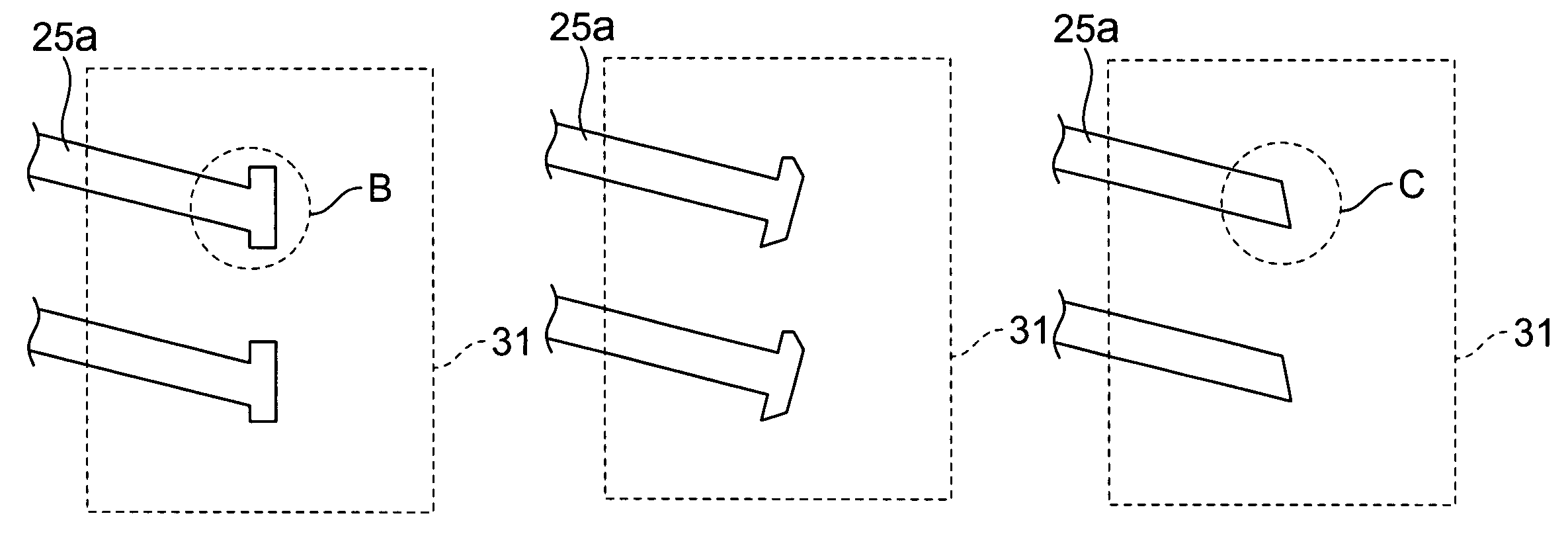
[0053]FIG. 6 is a plan view for schematically illustrating a shape of an edge portion of slit pattern 25a of a pixel electrode in an FFS-LCD according to the present invention.

[0054]As shown in FIG. 6, according to the first embodiment of the present invention, an edge portion of slit pattern 25a of the pixel electrode 25 having a linear line shape may be formed in a wedge shape A. Herein, the edge portion of slit pattern 25a of the pixel electrode 25, which has the wedge shape A, may be aligned in line with a central portion of the slit pattern of the pixel electrode 25 as shown in FIG. 6, or may be inclined from the central portion of the pixel electrode by a predetermined angle, which is not shown.

second embodiment

[0055]FIGS. 7 and 8 are plan views for schematically illustrating shapes of edge portions of slit pattern 25a of pixel electrodes in FFS-LCDs according to the present invention.

[0056]As shown in FIG. 7, according to the second embodiment of the present invention, an edge portion of slit pattern 25a of the pixel electrode 25 having a linear line shape includes a structure B, an end part of which is formed by two ‘’-shaped patterns protruding in opposition to each other. In addition, in the structure B having two ‘’-shaped patterns at the end part thereof, one side of each ‘’-shaped pattern may be inclined as shown in FIG. 8.

third embodiment

[0057]FIG. 9 is a plan view for schematically illustrating a shape of an edge portion of the slit pattern of a pixel electrode in an FF3-LCD according to the present invention.

[0058]As shown in FIG. 9, according to the third embodiment of the present invention, an edge portion of slit pattern 25a of the pixel electrode 25, which has a linear line shape, may be formed in a structure C in which one side face is inclined.


PUM

PropertyMeasurementUnit
angleaaaaaaaaaa
angleaaaaaaaaaa
oblique angleaaaaaaaaaa

Abstract

Disclosed is a fringe field switching liquid crystal display. The fringe field switching liquid crystal display comprises a black matrix formed on an upper substrate, a pixel electrode formed above a lower substrate and having an edge portion overlapped with the black matrix by a predetermined region, and liquid crystal interposed between the upper substrate and the lower substrate, wherein the edge portion of the pixel electrode has a linear line shape. According to such an edge portion of the pixel electrode, it is possible to stably drive the liquid crystal located at the edge portion of the pixel electrode and also to restore the liquid crystal with rapidity.

Description

BACKGROUND OF THE INVENTION[0001]1. Field of the Invention[0002]The present invention relates to a fringe field switching liquid crystal display (hereinafter, simply referred to as “FFS-LCD”), and more particularly to an FFS-LCD capable of preventing a misalignment of liquid crystal molecules caused by rubbing pressure in an FFS-LCD pixel structure, thereby preventing a display fault.[0003]2. Description of the Prior Art[0004]As generally known in the art, conventional thin-film liquid crystal displays (LCDs) are used as information display apparatuses, such as information display screens of portable terminals, displayers of notebook PCs, monitors of lap top computers, etc. Particularly, such liquid crystal displays have been widely used in various industrial fields in replacement of conventional CRT (cathode ray tube) monitors.[0005]FIG. 1 is a plan view for illustrating a conventional FFS-LCD.[0006]In addition, FIG. 2 is a view for showing a shape of a pixel electrode and a state ...

Claims


Application Information

Patent Timeline
Patent Type & Authority Patents(United States)
IPC IPC(8): G02F1/1343G02F1/133G02F1/1335G02F1/136G02F1/1368
CPCG02F1/133512G02F1/134363G02F1/1343
Inventor LEE, KYUNG HAAN, CHI WOOK
Owner BOE HYDIS TECH CO LTD
Why Eureka
Try Eureka