GMR sensor having a reference layer with movable magnetization

a reference layer and magnetization technology, applied in the field of giant magnetoresistive (gmr) magnetic field sensor fabrication, can solve the problems of unsatisfactory signal noise, sensitivity of free layers such as ultra-narrow trackwidths and thicknesses, and the ability of free layer magnetic moment to be weak, and achieve the effect of improving the signal respons

Active Publication Date: 2008-03-18
HEADWAY TECH INC
View PDF22 Cites 35 Cited by
  • Summary
  • Abstract
  • Description
  • Claims
  • Application Information

AI Technical Summary

Benefits of technology

[0014]The first object of this invention is to provide a GMR sensor in a spin valve configuration with narrow trackwidth and enhanced sensitivity.
[0015]A second object of the present invention is to provide such a sensor in which Barkhausen noise is eliminated or kept within very low limits.
[0022]Referring next to FIGS. 3a, b and c, there is shown a set of analogous representations of the free (thick arrow) and reference (thin arrow) layer magnetic moments of the present invention. In FIG. 3a, the magnetic moments in the absence of an external field are shown. Note that the angle between the arrows is greater than 90° and less than 270°. This is required in order for the motion of each arrow during a field transition to be in an opposite direction and for the relative motion of the arrows during transitions to always provide a greater angle and, therefore, to provide an enhanced signal response. FIG. 3b shows a + transition, showing the opposite motion of each arrow. FIG. 3c shows a − transition, again showing opposite motion of the magnetic moment.

Problems solved by technology

As the size of free layers decrease dramatically, there is a problem of maintaining a stable domain structure that will not be overly affected by temperature variations and produce undesirable signal noise (Barkhausen noise).
However, the sensitivity of free layers having such ultra-narrow trackwidths and thicknesses, which is the ability of the free layer magnetic moment to be rotated by the external fields of the recorded media, becomes worse as a result of the free layer edge demagnetization field and the longitudinal bias field from permanent magnets used to maintain a stable free layer domain structure.
As noted above, as the free layers become thinner and narrower, the edge pole compensation provided by the longitudinal bias layers actually begins to dominate the magnetic fields of the recorded media and the free layer stability becomes a loss of sensitivity.

Method used


Image

  • GMR sensor having a reference layer with movable magnetization
  • GMR sensor having a reference layer with movable magnetization
  • GMR sensor having a reference layer with movable magnetization

Examples


Embodiment Construction

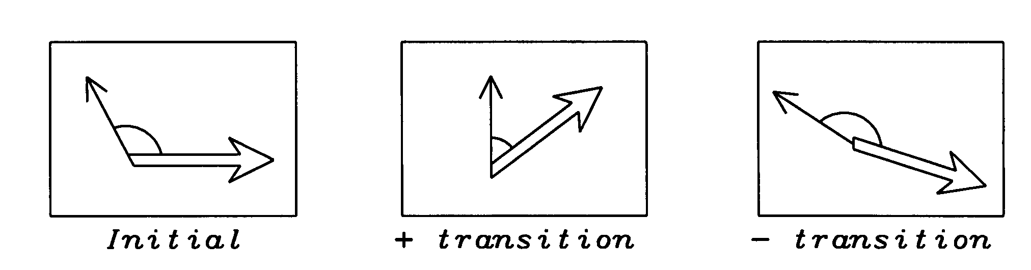
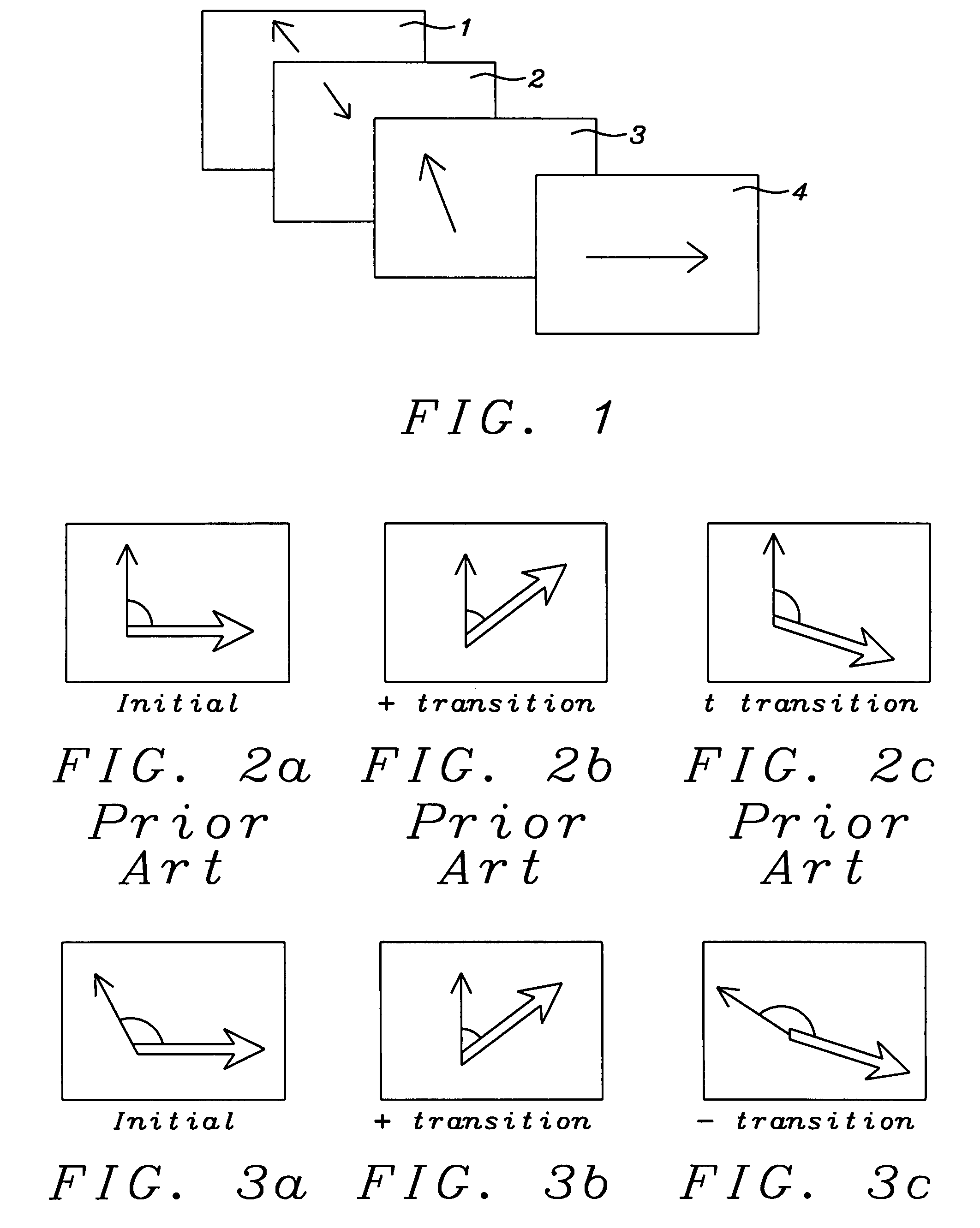
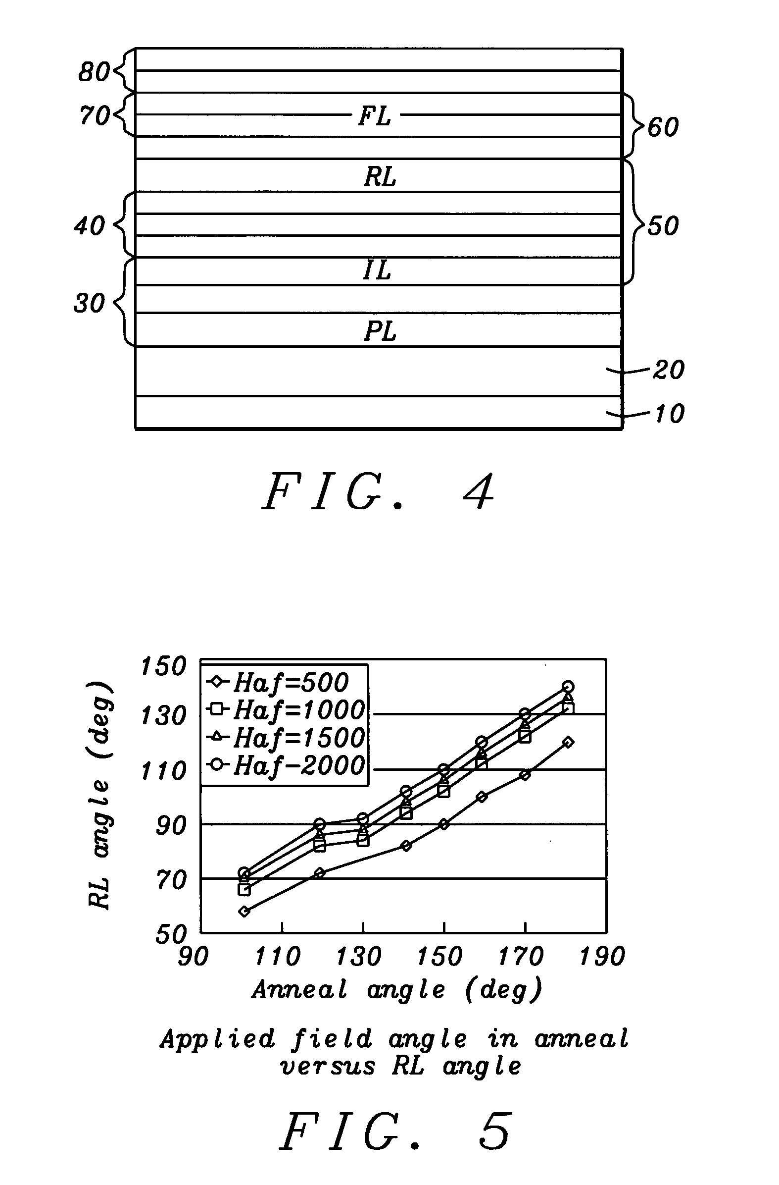
[0032]The present invention provides a modified spin-valve sensor having a synthetic antiferrimagnetic pinned reference layer, which is formed of three ferromagnetic layers, denoted PL, IL and RL (pinned layer, intermediate layer and reference layer) wherein each pair of layers is separated by a spacer layer and magnetized, by exchange coupling, as a synthetic ferrimagnet, SyF. The method of fabricating the sensor is also provided. A novel aspect of the invention is that the exchange coupling between PL and IL is stronger than that between IL and RL, so that the magnetic moment of RL is relatively free to move in the magnetic field of the recorded medium, while the PL / IL combination plays the role of a pinned layer. Because the annealing of the structure creates an angle between the magnetic moments of RL and the free layer, FL, that is between 90° and 270°, the free layer magnetization moves in an opposite direction to the RL magnetization under the influence of the external field....


PUM

PropertyMeasurementUnit
thicknessaaaaaaaaaa
thicknessaaaaaaaaaa
thicknessaaaaaaaaaa

Abstract

A method for fabricating a spin-valve GMR sensor having a reference layer with a magnetic moment that moves in an opposite direction to that of the free layer in the presence of external magnetic field transitions. The reference layer is a part of a three ferromagnetic layer structure, including pinned, intermediate and reference layers, that when the layers are taken pairwise and separated by spacer layers, includes a strongly exchange coupled synthetic ferrimagnetic pinned and intermediate layer pair and a weakly exchange coupled synthetic ferrimagnetic intermediate and reference layer pair. The reference layer, because of its weak coupling to the intermediate layer, has a magnetic moment that is free to move. During sensor operation, the reference layer and free layer move in opposite directions under the influence of external magnetic field transitions The novel three layer structure provides a sensor of increased sensitivity for a given track width.

Description

BACKGROUND OF THE INVENTION[0001]1. Field of the Invention[0002]This invention relates generally to the fabrication of a giant magnetoresistive (GMR) magnetic field sensor for a magnetic read head. More particularly, it relates to such a sensor with a reference (pinned) layer whose magnetization varies in direction.[0003]2. Description of the Related Art[0004]The giant magnetoresistive (GMR) sensor of the “spin-valve” (SV) configuration is a multi-layered configuration of magnetic and non-magnetic layers which includes a magnetically free layer, whose magnetic moment is free to respond to external magnetic stimuli, separated by a non-magnetic layer from a magnetically “pinned” layer, called the reference layer, whose magnetic moment is fixed in direction.[0005]Typically, the magnetic moment of a reference layer is most effectively pinned by forming the reference layer as a laminated three layer structure, called a synthetic ferrimagnet (SyF). The SyF is formed as two layers of ferro...

Claims


Application Information

Patent Timeline
Patent Type & Authority Patents(United States)
IPC IPC(8): G11B5/33G11B5/127
CPCG11B5/39G11B5/3903G11B5/3932
Inventor TAKANO, KENICHI
Owner HEADWAY TECH INC
Why Eureka
Try Eureka