Non-influencing fastener for mounting a heat sink in contact with an electronic component

a technology of electronic components and fasteners, which is applied in the direction of machine supports, furniture parts, lighting and heating apparatus, etc., can solve the problems of reducing the performance of electronic components, reliability, life expectancy, volume and mass of heatsinks, and bare dies cannot support the mass of heatsinks alone, and achieve good contact interface

Active Publication Date: 2008-03-18
LENOVO GLOBAL TECH INT LTD
View PDF14 Cites 15 Cited by
  • Summary
  • Abstract
  • Description
  • Claims
  • Application Information

AI Technical Summary

Benefits of technology

[0012]In a further aspect of the invention, a heat transfer apparatus comprises a load frame having an open region exposing a surface of an electronic component; a heat sink disposed on the load frame and having a surface in thermal contact with the surface of the electronic component through a thermally conductive material, the load frame applying a preload force to the heat sink to compress the thermally conductive material and achieve a desired thermal interface gap between the surface of the heat sink and the surface of the electronic component; and at least one non-influencing fastener disposed within a bore of the heat sink and threaded into the load frame to secure the heat sink to the load frame and maintain the desired thermal interface. Each of the non-influencing fasteners includes a screw with a head; a tapered ring disposed on the screw below the head of the screw and having a tapered lower peripheral surface; and a sealing ring disposed on the screw and engaging the tapered lower peripheral surface of the tapered ring, such that compression of the rings by turning of the screw into the load frame causes the sealing ring to expand against the bore of the heatsink. Placing the tapered ring above the sealing ring on the screw advantageously stabilizes the expanding sealing ring on the load frame, thereby isolating any axial motion with respect to the heat sink. Having an external radius on the sealing ring allows a good contact interface with the heat sink bore even if axial misalignment is introduced between the fastener and the heat sink.

Problems solved by technology

Excessive heat degrades electronic component performance, reliability, life expectancy, and can even cause failure.
However, as component power dissipation increases, the volume and mass of the heatsink increase accordingly, and the bare die can no longer support the mass of the heatsink alone.

Method used


Image

  • Non-influencing fastener for mounting a heat sink in contact with an electronic component
  • Non-influencing fastener for mounting a heat sink in contact with an electronic component
  • Non-influencing fastener for mounting a heat sink in contact with an electronic component

Examples


Embodiment Construction

[0020]The invention will now be described in more detail by way of example with reference to the embodiments shown in the accompanying figures, where like designations denote like elements. It should be kept in mind that the following described embodiments are only presented by way of example and should not be construed as limiting the inventive concept to any particular physical configuration.

[0021]Further, if used and unless otherwise stated, the terms “upper,”“lower,”“front,”“back,”“over,”“under,” and similar such terms are not to be construed as limiting the invention to a particular orientation. Instead, these terms are used only on a relative basis.

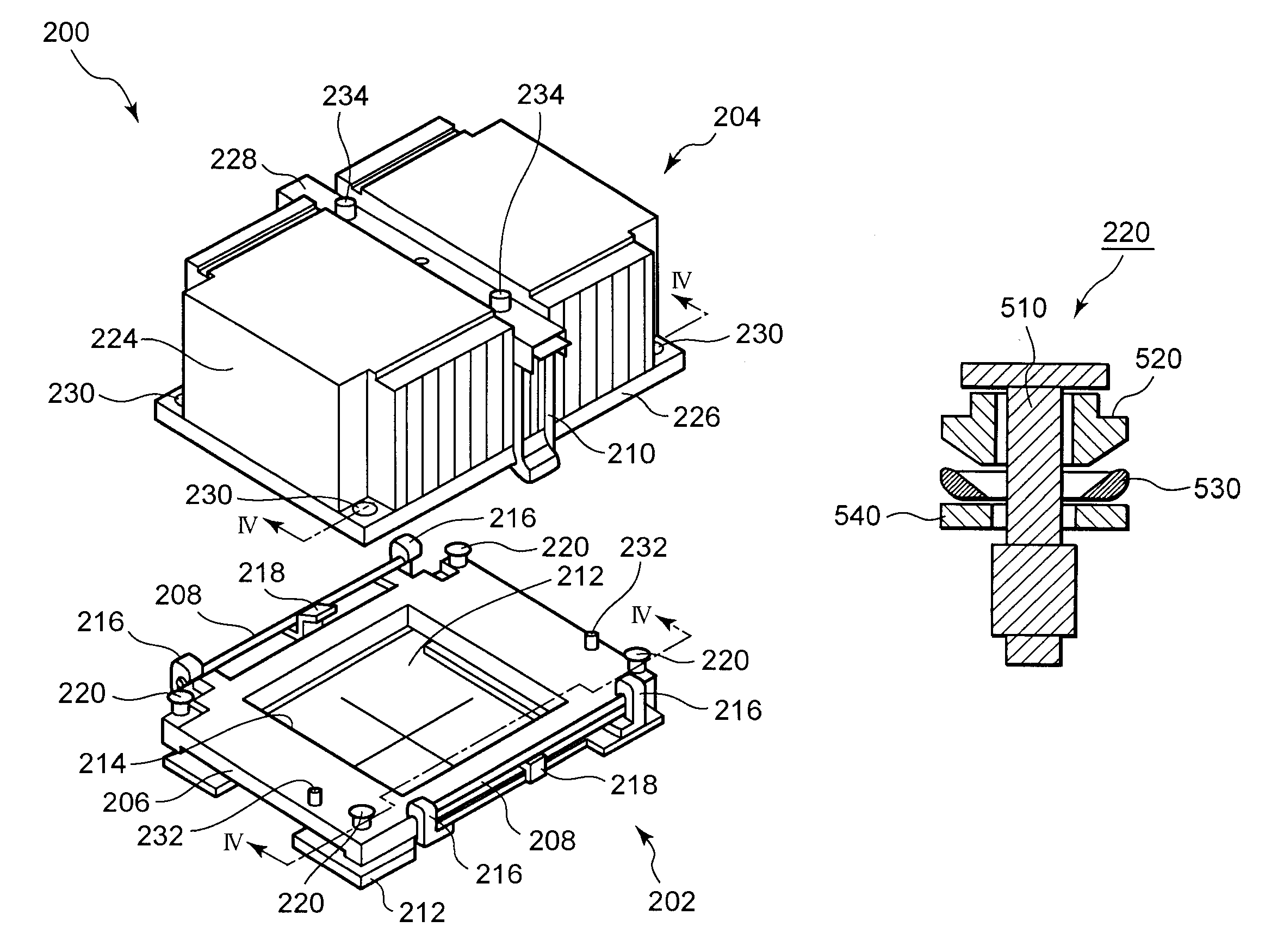
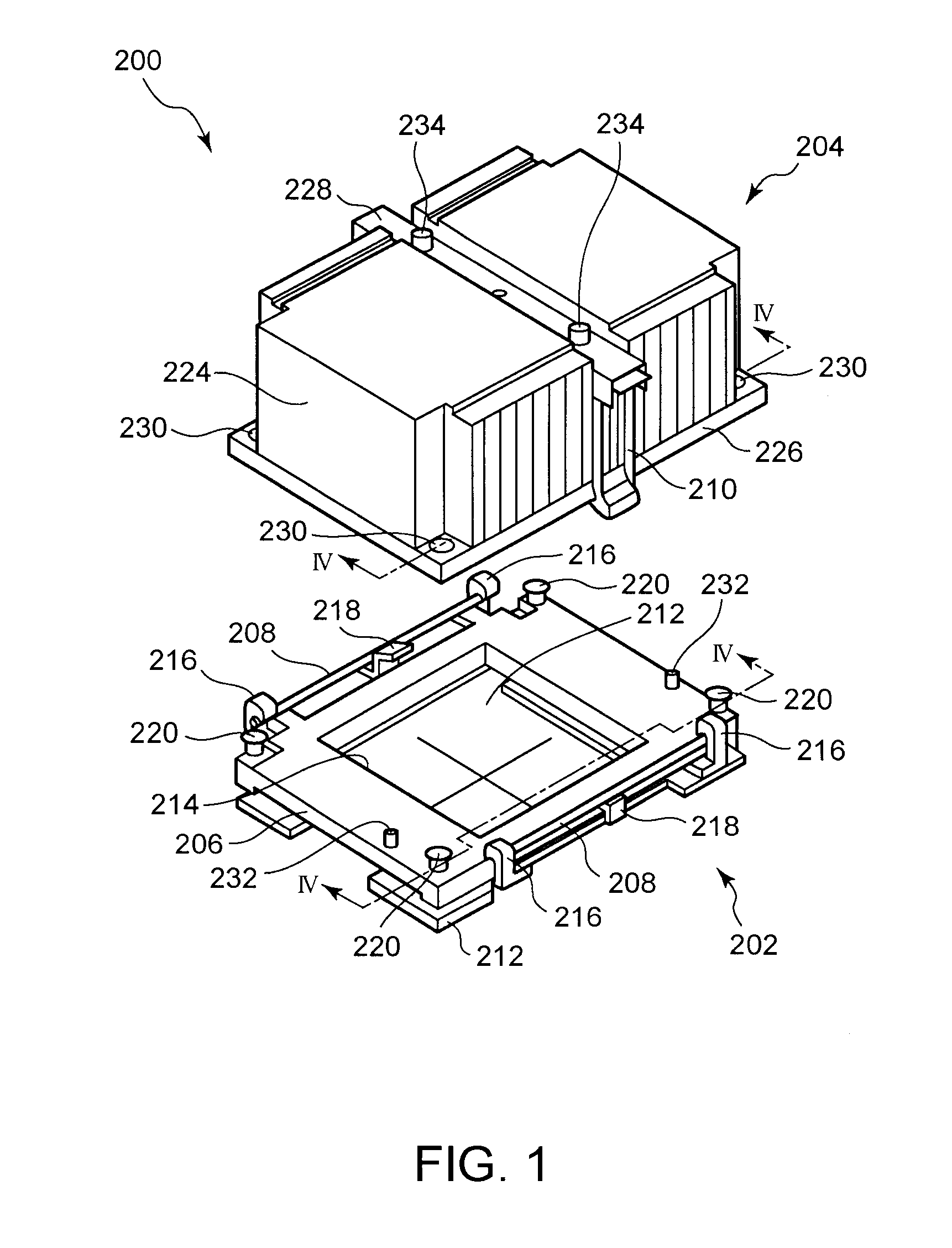
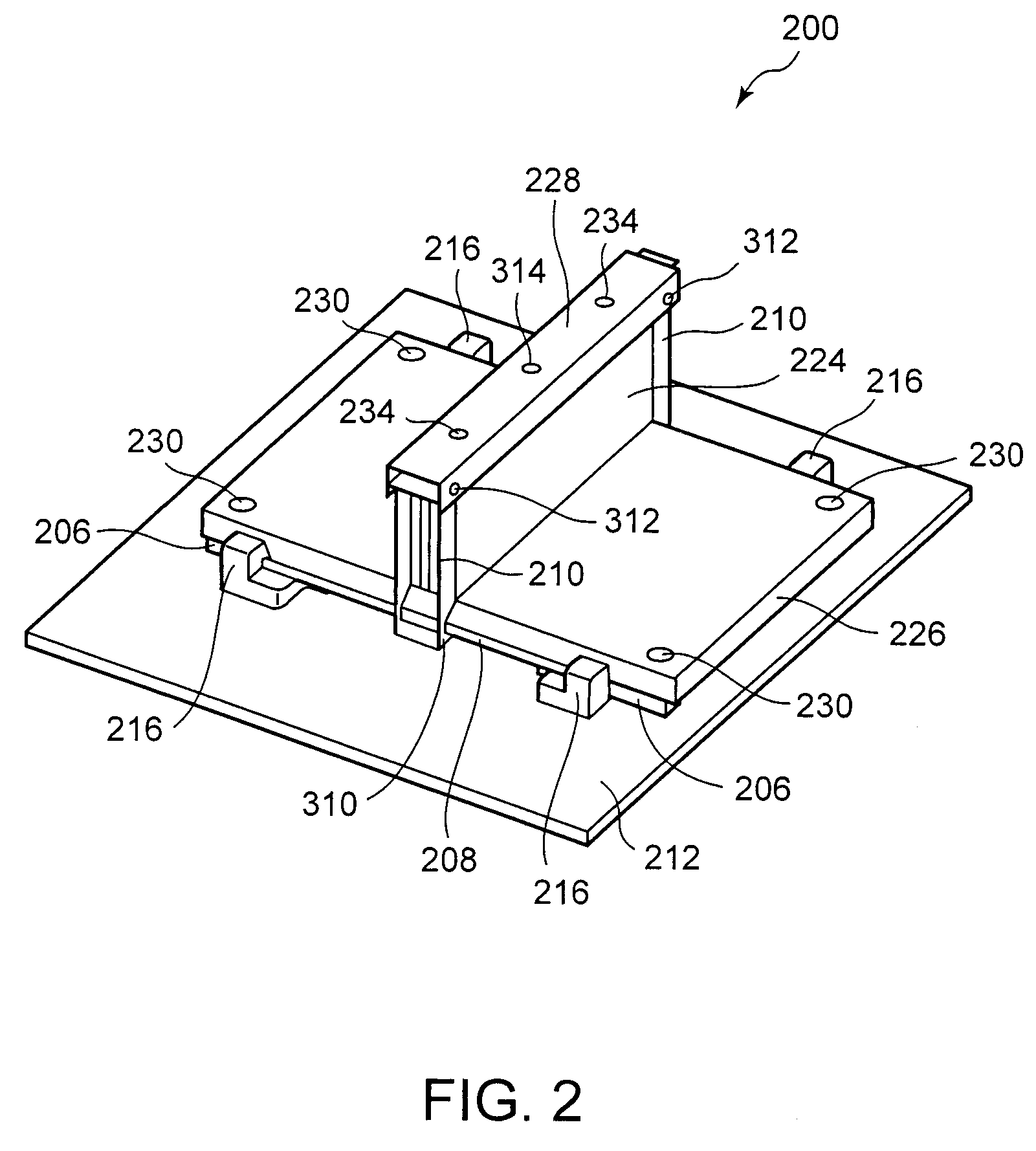
[0022]Reference is now made to FIGS. 1-3 for illustrating an exemplary heat transfer apparatus 200 incorporating a preferred embodiment of the inventive non-influencing fastener for mounting a heat sink on a heat source, such as an electronic component. FIGS. 1-3 are intended to depict the representative major components of heat tra...


PUM


Abstract

A load frame has an open region exposing a surface of an electronic component. A heat sink is disposed on the load frame and has a surface in thermal contact with the surface of the electronic component. A non-influencing fastener is disposed within a bore in the heat sink and threaded into the load frame for securing the heat sink to the load frame. The non-influencing fastener includes a screw with a head; a tapered ring disposed below the head of the screw and having a tapered lower peripheral surface; a sealing ring engaging the tapered lower peripheral surface of the tapered ring; and a load washer disposed between the sealing ring and the load frame. Compression of the rings by turning of the screw into the load frame causes the sealing ring to expand against the bore of the heatsink. Preferably, the sealing ring has a curved outer surface.

Description

BACKGROUND OF THE INVENTION[0001]1. Field of the Invention[0002]The invention relates to a non-influencing fastener, and specifically to a non-influencing fastener for mounting a heat sink in contact with an electronic component.[0003]2. Background Information[0004]Electronic components, such as microprocessors and integrated circuits, must operate within certain specified temperature ranges to perform properly. Excessive heat degrades electronic component performance, reliability, life expectancy, and can even cause failure. Heat sinks are widely used for dissipating excessive heat. Typically, heat sinks are formed with fins, pins or other similar structures to increase the surface area of the heat sink and thereby enhance heat dissipation as air passes over the heat sink. Where large amounts of heat are to be dissipated, heat sinks may contain high performance structures, such as vapor chambers and / or heat pipes, to further enhance heat transfer. Heat sinks are typically formed of...

Claims


Application Information

Patent Timeline
Patent Type & Authority Patents(United States)
IPC IPC(8): H05K7/20
CPCH01L23/4006H01L2023/405H01L2023/4062Y10T24/44026H01L2023/4087H01L2224/16225Y10T24/44017H01L2023/4081
Inventor COLBERT, JOHN LEECORBIN, JR., JOHN SAUNDERSECKBERG, ERIC ALANGERKEN, JAMES DORANCEHAMILTON, ROGER DUANEHOLAHAN, MAURICE FRANCIS
Owner LENOVO GLOBAL TECH INT LTD
Why Eureka
Try Eureka