Catalytic converter and manufacturing method thereof

a technology of catalytic converter and manufacturing method, which is applied in the direction of physical/chemical process catalyst, metal/metal-oxide/metal-hydroxide catalyst, separation process, etc., can solve the problem that the catalytic function cannot be fully exerted

Active Publication Date: 2008-12-25
NISSAN MOTOR CO LTD
View PDF7 Cites 10 Cited by
  • Summary
  • Abstract
  • Description
  • Claims
  • Application Information

AI Technical Summary

Benefits of technology

[0011]The second aspect of the present invention provides a manufacturing method of the catalytic converter, the method comprising: dispersing, in a solvent, the catalyst component and a disappearing material disappearing by heat, thereby obtaining a slurry; coating the obtained slurry on the three-dimensional structural support; and baking the slurry-coated three-dimensional structural support to eliminate the disappearing material.
[0012]The third aspect of the present invention provides a manufacturing method of the catalytic converter, the method comprising: dispersing, in a first solvent, a disappearing material disappearing by heat, thereby obtaining a disappearing material slurry; coating the disappearing material slurry on the three-dimensional structural support, followed by drying, thereby forming a disappearing material-coated layer; further coating a catalyst slurry, in which the catalyst component is dispersed in a second solvent, on the three-dimensional structural support on which the disappearing material-coated layer is formed; and baking the catalyst slurry-coated three-dimensional structural support to eliminate the disappearing material.

Problems solved by technology

However, since the trapped particulates are accumulated on a surface of the filter, the particulate removing catalyst described in Japanese Patent Unexamined Publication No. 2002-102621 has had a problem that the catalytic function cannot be fully exerted unless contact interfaces between the catalyst layer and the particulates are increased.

Method used


Image

  • Catalytic converter and manufacturing method thereof
  • Catalytic converter and manufacturing method thereof
  • Catalytic converter and manufacturing method thereof

Examples


example 1

[0038]450 g of cerium oxide powder, 125 g of activated carbon, and 50 g of alumina sol were mixed into 2000 g of water, followed by stirring, whereby a catalyst slurry was prepared.

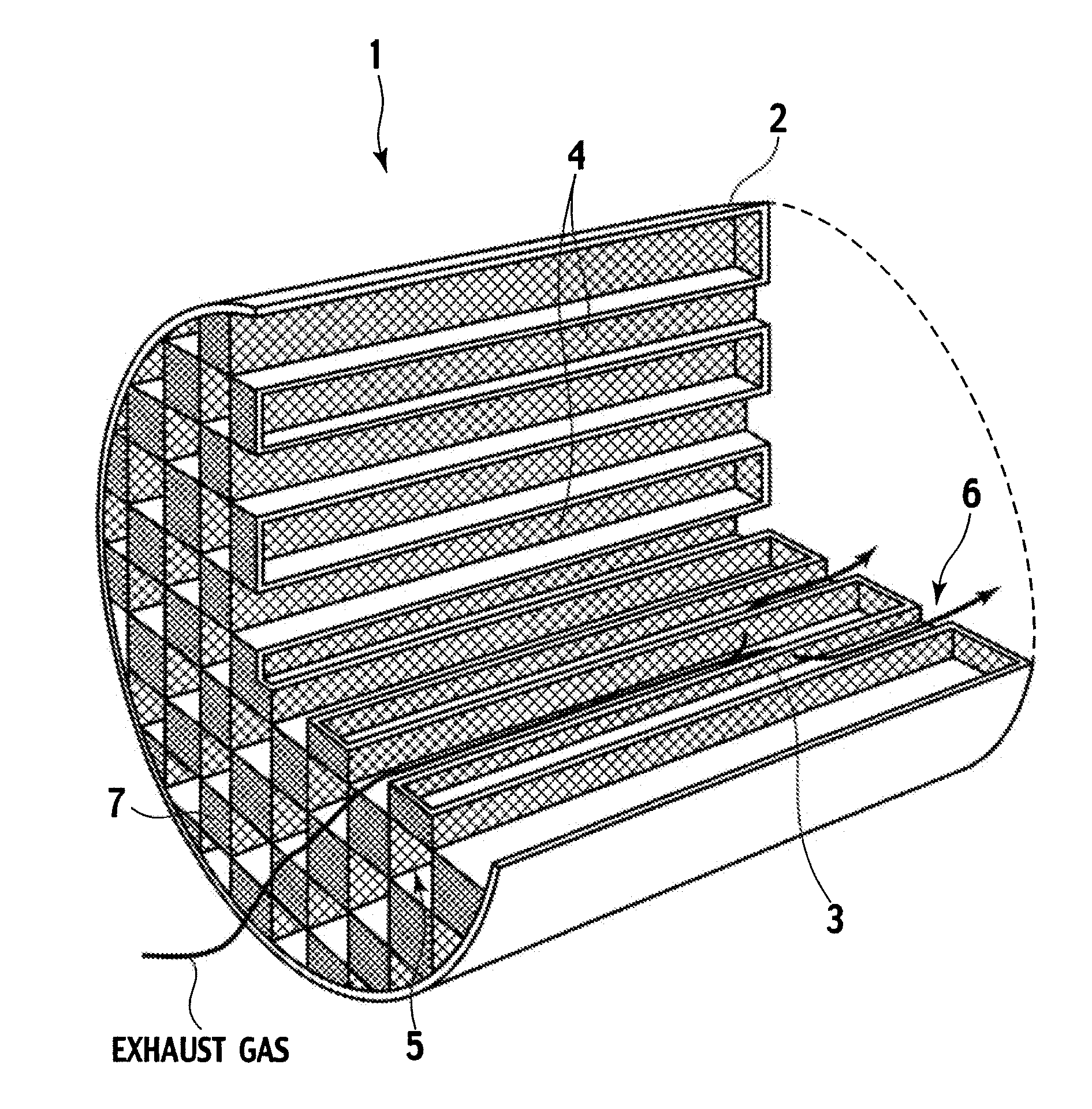
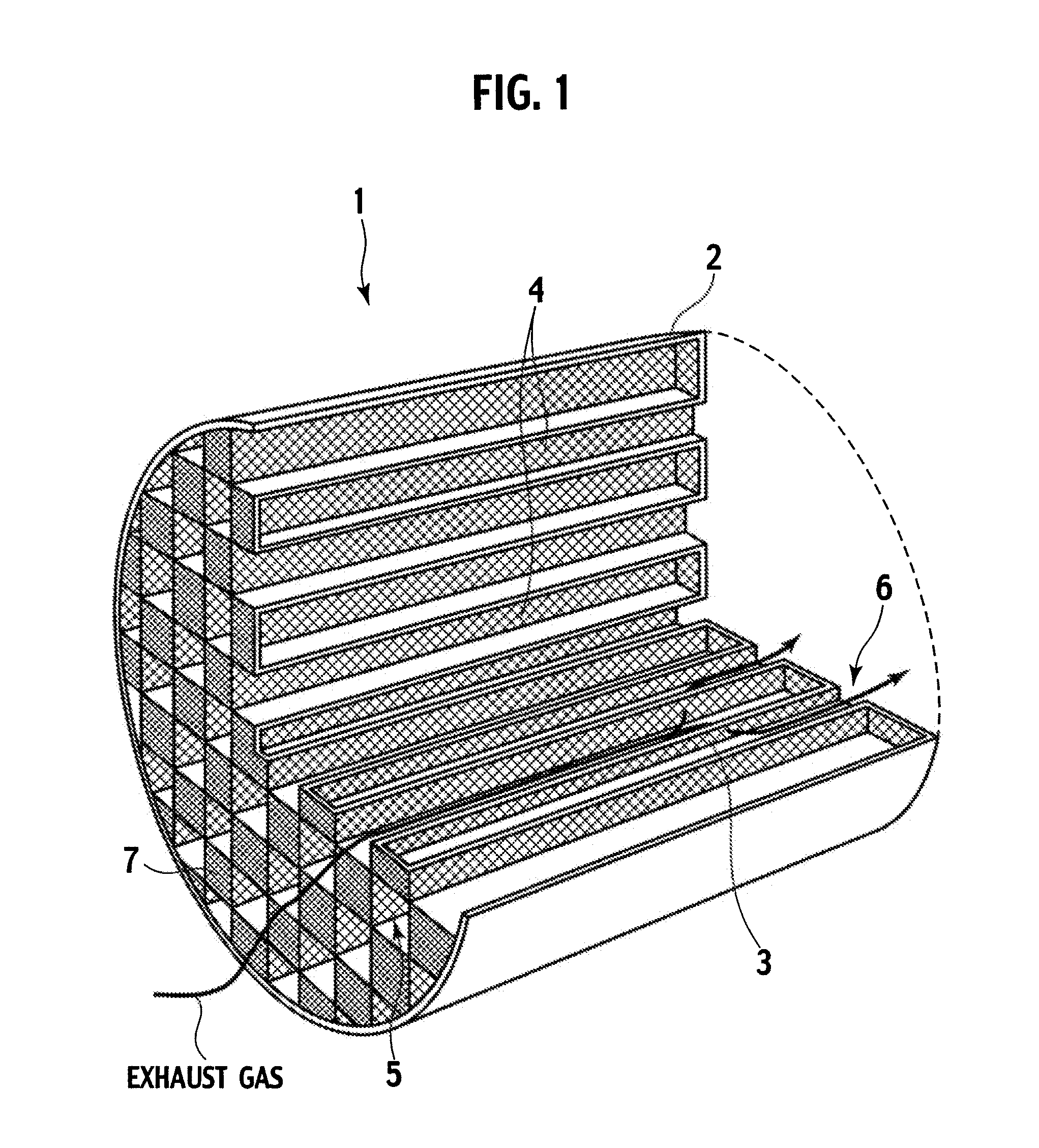
[0039]Next, a SiC-made honeycomb support was prepared, in which a diameter was 144 mm, a height was 152 mm, a cell density was 400 / in2, a center pore diameter in the cell wall was 10 to 20 μm, and porosity was 50 to 60 vol %. This honeycomb support was immersed into the above-described catalyst slurry, and excessive catalyst slurry was then removed therefrom, followed by drying at 150° C. for two hours and baking at 400° C. for four hours. In such a way, a catalyst layer was formed on the honeycomb support, and a catalytic converter of this Example was obtained. A formed amount of the catalyst layer was 50 g per liter of the catalytic converter.

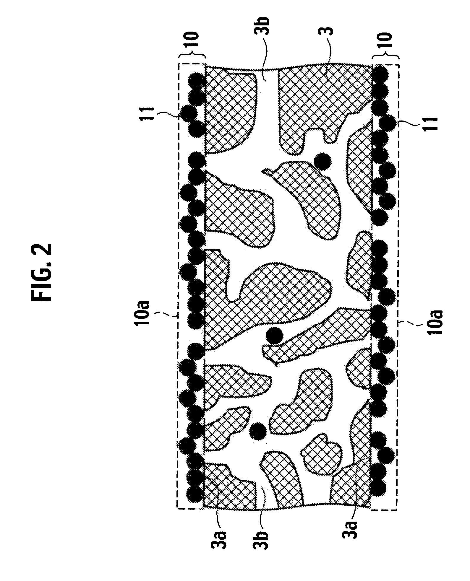
[0040]FIG. 5 shows the SEM picture of a vicinity of the corner of the honeycomb in the catalytic converter of this Example. From FIG. 5, the following is understoo...

example 2

[0042]450 g of cerium / praseodymium composite oxide powder, 125 g of activated carbon, and 50 g of alumina sol were mixed into 2000 g of water, followed by stirring, whereby a catalyst slurry was prepared.

[0043]Next, the SiC-made honeycomb support used in Example 1 was prepared, and was immersed into the catalyst slurry, and excessive catalyst slurry was then removed therefrom, followed by drying at 150° C. for two hours and baking at 400° C. for four hours. In such a way, a catalyst layer was formed on the honeycomb support, and a catalytic converter of this Example was obtained. A formed amount of the catalyst layer was 50 g per liter of the catalytic converter. 82% of the total supported amount of the catalyst component was coated on the surface of the support.

example 3

[0044]450 g of cerium / yttrium composite oxide powder, 125 g of activated carbon, and 50 g of alumina sol were mixed into 2000 g of water, followed by stirring, whereby a catalyst slurry was prepared.

[0045]Next, the SiC-made honeycomb support used in Example 1 was prepared, and was immersed into the catalyst slurry, and excessive catalyst slurry was then removed therefrom, followed by drying at 150° C. for two hours and baking at 400° C. for four hours. In such a way, a catalyst layer was formed on the honeycomb support, and a catalytic converter of this Example was obtained. A formed amount of the catalyst layer was 50 g per liter of the catalytic converter. 82% of the total supported amount of the catalyst component was coated on the surface of the support.


PUM

PropertyMeasurementUnit
pore diameteraaaaaaaaaa
particle diameteraaaaaaaaaa
pore diameteraaaaaaaaaa

Abstract

A catalytic converter includes: a three-dimensional structural support having a plurality of cells partitioned by porous cell walls, in which a pore diameter of the cell walls is 10 μm to 50 μm and porosity of the cell walls is 40 vol % or more; and a catalyst-coated layer containing a catalyst component. The catalyst-coated layer is coated on surfaces of the cell walls of the three-dimensional structural support. 50 mass % or more of a total supported amount of the catalyst component on the three-dimensional structural support is present in a region from the surfaces of the cell walls of the three-dimensional structural support to surfaces of the catalyst-coated layer.

Description

BACKGROUND OF THE INVENTION[0001]1. Field of the Invention[0002]The present invention relates to a catalytic converter and a manufacturing method thereof. More specifically, the present invention relates to a catalytic converter capable of effectively utilizing a catalyst component supported thereon, and to a manufacturing method of the catalytic converter.[0003]2. Description of the Related Art[0004]Heretofore, in a gasoline engine, technologies for exhaust gas purification have been advanced following strict regulation for exhaust gas, and harmful substances contained in the exhaust gas have been surely being reduced. However, since a diesel engine has particularity to emit harmful components in a form of particulates, legal regulation for the harmful components and technical development for purification thereof have been delayed in comparison with those of the gasoline engine.[0005]However, with regard to the particulates emitted from an internal combustion engine of an automobil...

Claims


Application Information

Patent Timeline
Patent Type & Authority Applications(United States)
IPC IPC(8): B01D53/86B05D3/02
CPCB01D53/944B01D53/9454B01D2255/10B01D2255/20B01D2255/20715B01D2255/2092B01D2255/92B01D2255/9205B01D2258/012B01J23/10B01J23/40B01J23/63B01J35/04B01J37/0018B01J37/0219B01J37/0228B01J37/0244B01J37/0248B01J37/084B22F3/1121B22F2998/00B22F1/025Y02T10/22Y02T10/12B22F1/18
Inventor MORISAKA, HIDEAKITAKAYA, MASAHIROMIYAMURA, TOSHIHARUYAMAUCHI, TAKESHIHANAKI, YASUNARI
Owner NISSAN MOTOR CO LTD
Why Eureka
Try Eureka