Heat-dissipating fan

a technology of heat dissipation fan and fan body, which is applied in the direction of machines/engines, liquid fuel engines, light and heating apparatus, etc., can solve the problems of shortening adversely affecting the operation stability of electronic components, and excessive high temperature, so as to prolong the life of heat dissipation fans and improve heat dissipation efficiency

Inactive Publication Date: 2008-03-18
SUNONWEALTH ELECTRIC MACHINE IND
View PDF21 Cites 53 Cited by
  • Summary
  • Abstract
  • Description
  • Claims
  • Application Information

AI Technical Summary

Benefits of technology

[0006]An object of the present invention is to provide a heat-dissipating fan with improved heat-dissipating efficiency for the electronic element, thereby prolonging the life of the heat-dissipating fan.
[0007]Another object of the present invention is to provide a heat-dissipating fan that provides a turbulence-reducing effect and that has a low noise during operation.SUMMARY OF THE INVENTION

Problems solved by technology

The electronic element 32 is generally mounted in a range of the base 13 and the hub 21 and lacks mechanism for dissipating the heat generated by the electronic element 32, resulting in excessively high temperature and adversely affecting operational stability of the electronic element 32 and even shortening the life of the heat-dissipating fan.

Method used


Image

  • Heat-dissipating fan
  • Heat-dissipating fan
  • Heat-dissipating fan

Examples


first embodiment

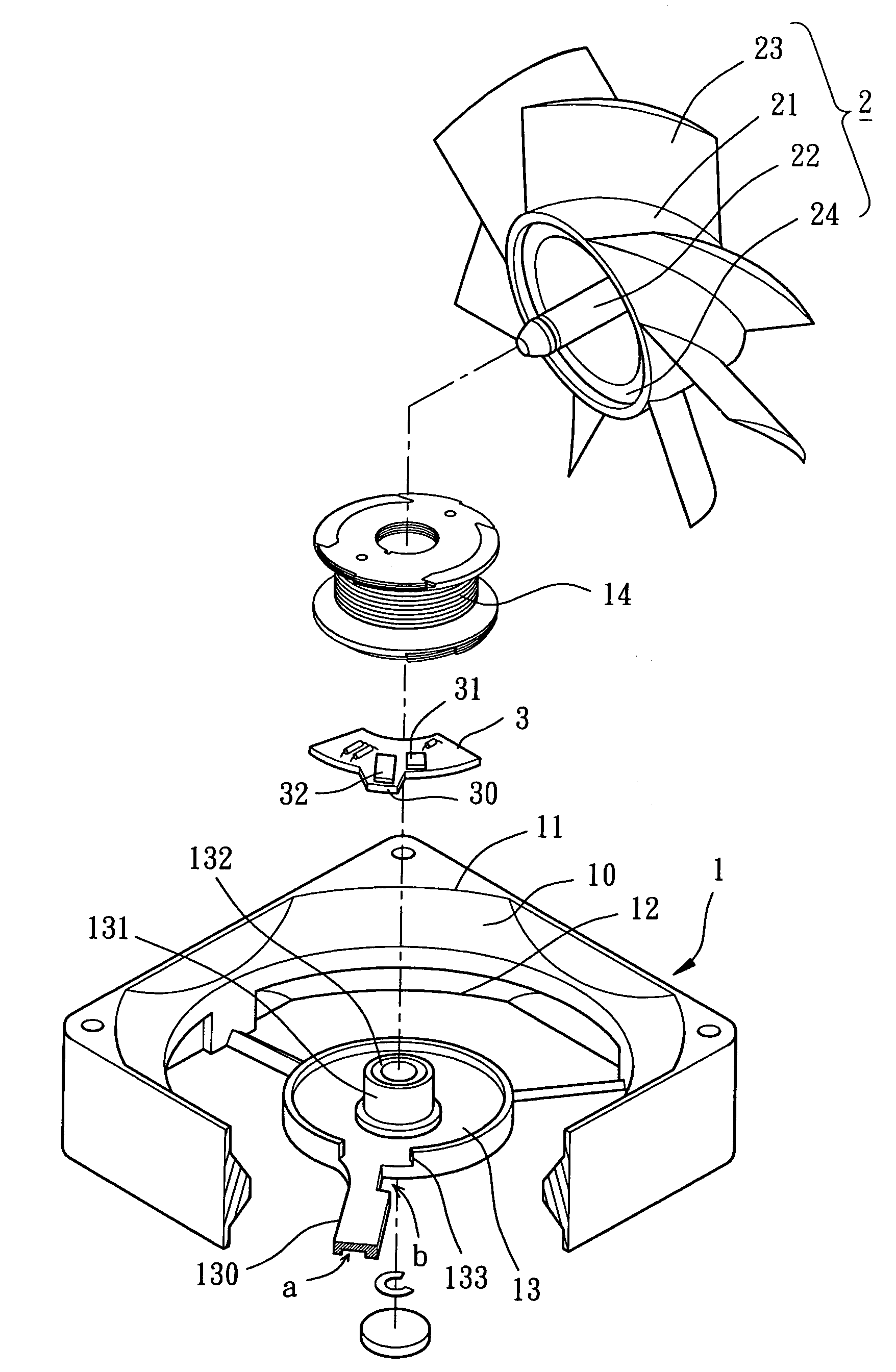
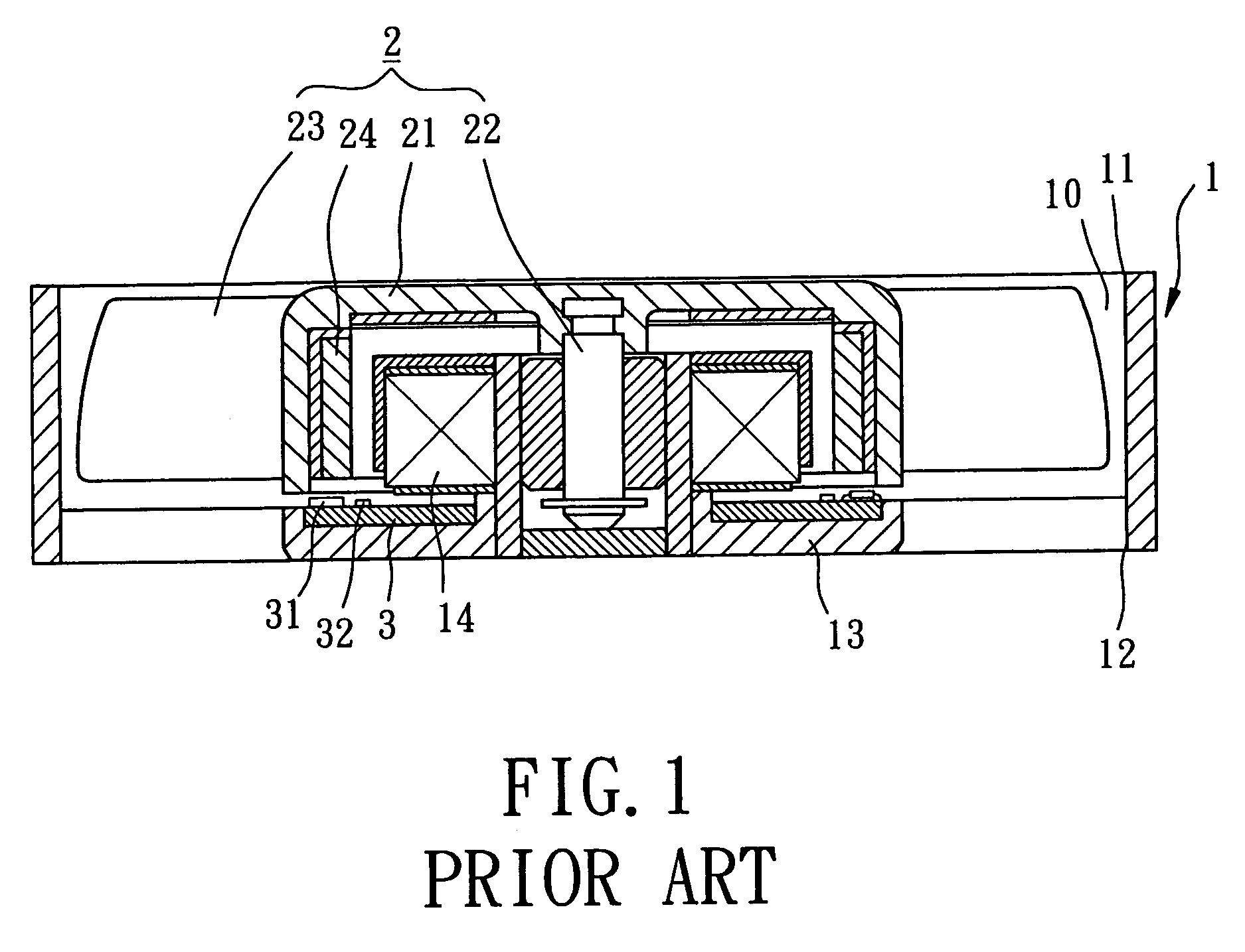
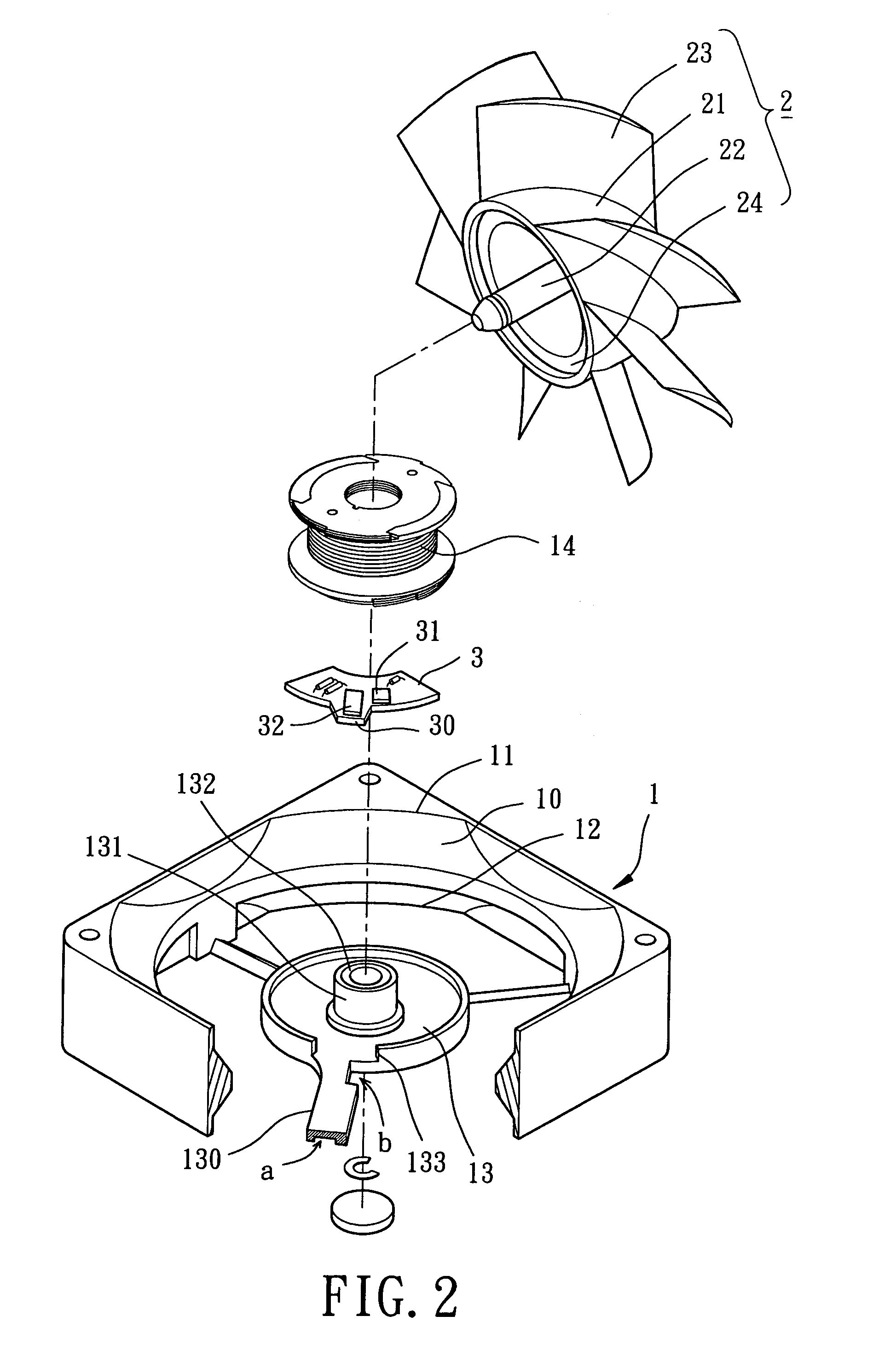
[0028]Referring to FIG. 2, a heat-dissipating fan in accordance with the present invention comprises a housing 1, an impeller 2, and a circuit board 3. The circuit board 3 is in a predetermined position relative to the housing 1 and the impeller 2 to prolong the life of the circuit board 3.

[0029]Referring to FIGS. 2 and 3, the housing 1 of the first embodiment comprises an air channel 10, an air inlet 11, an air outlet 12, and a base 13, and further accommodates a stator 14. The impeller 2 is received in the air channel 10. The air inlet 11 and the air outlet 12 are respectively at two ends of the air channel 10. Air currents enter the air channel 10 via the air inlet 11 and exit the air channel 10 via the air outlet 12.

[0030]The base 13 is selectively mounted on the air outlet 12 side or the air inlet 11 side. The base 13 comprises a plurality of ribs 130, an axial tube 131, at least one bearing 132, and at least one notch 133. The ribs 130 are mounted between the base 13 and an in...

third embodiment

[0037]Optionally, at least one balancing plate 15 can be mounted on the circuit board 3′ for preventing warping of the circuit board 3′. The balancing plate 15 is preferably made of magnetically conductive material such as iron or iron alloy. The balancing plate 15 is aligned with the annular magnet 24. Hence, a magnetic balancing attractive force is provided between the balancing plate 15 and the annular magnet 24. Thus, the third embodiment not only improves the heat-dissipating efficiency and increases mounting space but also enhances the rotational balance of the impeller 2.


PUM


Abstract

A heat-dissipating fan includes a housing, an impeller, and a circuit board. The housing includes an air channel and a base. The base is mounted in one end of the air channel for supporting the circuit board. The impeller is rotatably mounted on the base and includes a hub and a plurality of blades. The circuit board includes at least one heat-generating electronic element mounted thereon. The heat-generating electronic element extends out of the hub in relation to a longitudinal direction of the housing, with at least one portion of the heat-generating electronic element located on a downstream side of the blades for dissipating heat generated by the heat-generating electronic element.

Description

BACKGROUND OF THE INVENTION[0001]1. Field of the Invention[0002]The present invention relates to a heat-dissipating fan and more particularly to a heat-dissipating fan for lowering temperature of at least one heat-generating electronic element by mounting the heat-generating electronic element on a downstream side of the blades of an impeller of the heat-dissipating fan.[0003]2. Description of Related Art[0004]A conventional heat-dissipating fan, as illustrated in FIG. 1 of the drawings, comprises a housing 1, an impeller 2, and a circuit board 3. The housing 1 comprises an air channel 10, an air inlet 11, an air outlet 12, and a base 13, and further accommodates a stator 14. The impeller 2 is received in the air channel 10. Air currents enter the air channel 10 via the air inlet 11 and exit the air channel 10 via the air outlet 12. The circuit board 3 and the stator 14 are mounted on the base 13, which is mounted on the air outlet 12 side. The impeller 2 is coupled to the base 13 a...

Claims


Application Information

Patent Timeline
Patent Type & Authority Patents(United States)
IPC IPC(8): H05K7/20F28D15/00
CPCF04D29/582F04D25/0633
Inventor HORNG, ALEXSHIEH, HAO-ANLO, PEI-WEI
Owner SUNONWEALTH ELECTRIC MACHINE IND
Why Eureka
Try Eureka