Memory device

a memory device and memory technology, applied in the field of memory devices, can solve the problems of increased consumption current, difficulty in and difficulty in memory device high-speed driving, so as to achieve easy patterning in memory element manufacturing and high-speed driving of memory elements

Active Publication Date: 2008-03-18
SONY SEMICON SOLUTIONS CORP
View PDF4 Cites 24 Cited by
  • Summary
  • Abstract
  • Description
  • Claims
  • Application Information

AI Technical Summary

Benefits of technology

[0049]Specifically, in the source line drive method, VDD needs to be applied to the selected source line when data 1 is written. Applying VDD to all the source lines leads to increased consumption current and difficulty in high-speed driving of the memory elements compared with application of VDD to a single source line.
[0050]In the collective erasing method, VDD needs to be applied to the selected source line at the time of the first writing or second writing. Specifically, when initially data 0 is written to all the memory cells and then data 1 is written in accordance with input data, VDD needs to be applied to the selected source line in the second writing. In contrast, when initially data 1 is written to all the memory cells and then data 0 is written in accordance with input data, VDD needs to be applied to the selected source line in the first writing. Applying VDD to all the source lines leads to increased consumption current and difficulty in high-speed driving of the memory elements compared with application of VDD to a single source line.
[0054]Since the first electrode of the memory elements in the same memory block is formed of a single layer in common to the memory elements, there is no need to, in manufacturing of the memory elements, implement local patterning processing or the like on each memory cell basis for the first electrode formed in common to the memory elements. Therefore, the strictness of the patterning accuracy is eased, which allows the patterning to be carried out easily.
[0056]According to the above-described memory device of the embodiment of the invention, patterning can be carried out easily in manufacturing of memory elements, and the high-speed driving of the memory elements can be achieved.

Problems solved by technology

However, if this technique in which the ion feed layer for the memory elements is not patterned into individual layers for each memory cell but is provided in common to all the memory cells is employed, i.e., if a memory device is configured so that a common potential is applied to all the source lines, it is difficult to drive the memory elements in the memory device at a high speed.
Applying VDD to all the source lines leads to increased consumption current and difficulty in high-speed driving of the memory elements compared with application of VDD to a single source line.

Method used


Image

  • Memory device
  • Memory device
  • Memory device

Examples


first embodiment

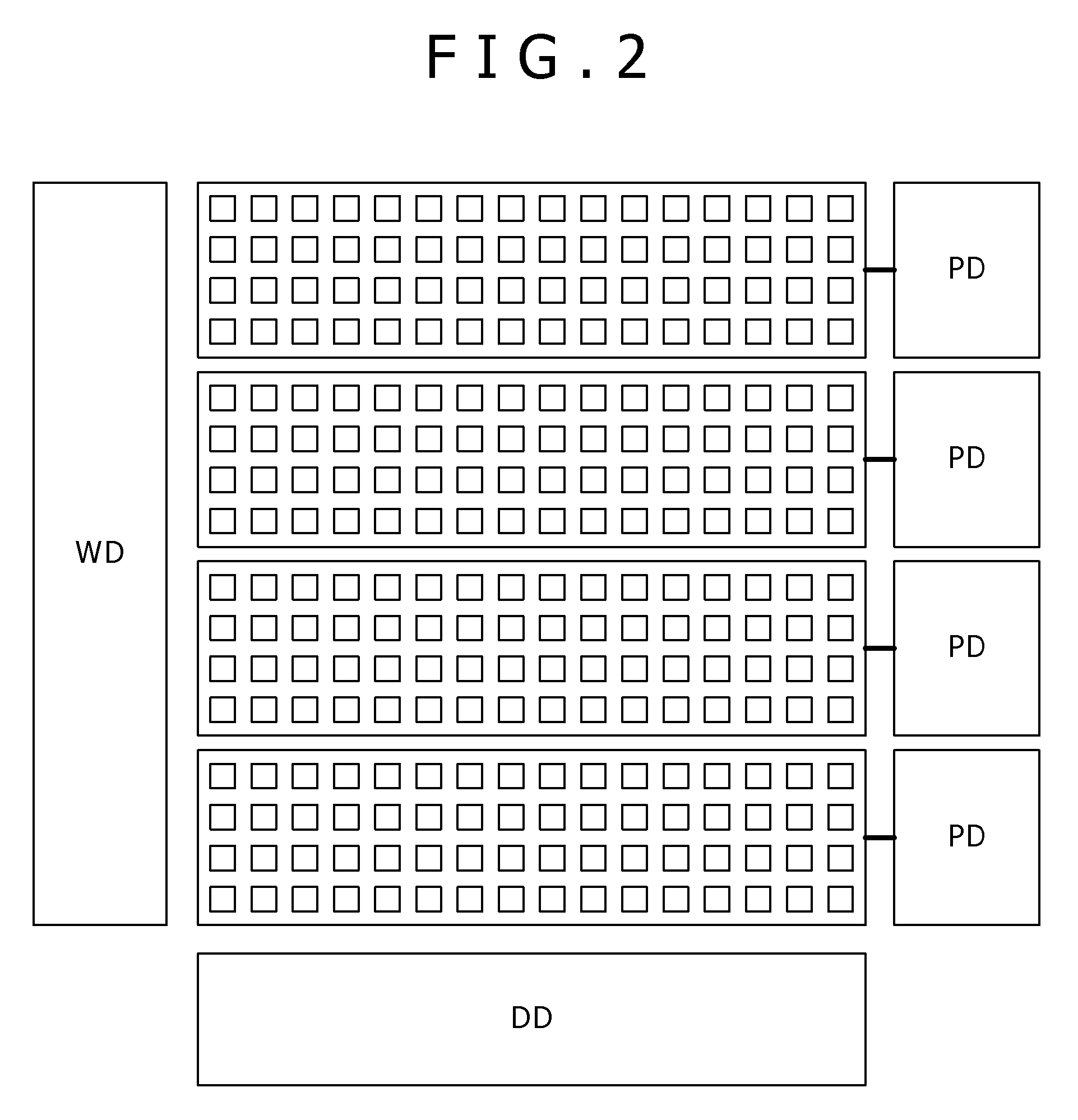
[0085]FIG. 2 is a schematic diagram for explaining a memory device in which each unit memory block includes memory cells of horizontal 16 bits by vertical 4 bits.

[0086]In the memory device shown in the drawing, a memory array of 256 bits includes four unit memory blocks each having memory cells of horizontal 16 bits by vertical 4 bits, and the four memory blocks are arranged along the vertical direction. The memory elements of the memory cells in each unit memory block (horizontal 16 bits by vertical 4 bits) are formed of a single high resistance film, a single ion source layer and a single upper electrode. Specifically, in the first embodiment, a single plate is quadrisected along the vertical direction so that four separated plates are formed.

[0087]The word lines are connected to a word driver WD, and the bit lines are connected to a data driver DD. Each of the upper electrodes of the respective separated plates is connected to a corresponding plate driver PD. Specifically, the up...

second embodiment

[0090]FIG. 3 is a schematic diagram for explaining a memory device in which each unit memory block includes memory cells of horizontal 4 bits by vertical 16 bits.

[0091]In the memory device shown in the drawing, a memory array of 256 bits includes four unit memory blocks each having memory cells of horizontal 4 bits by vertical 16 bits, and the four memory blocks are arranged along the horizontal direction. The memory elements of the memory cells in each unit memory block (horizontal 4 bits by vertical 16 bits) are formed of a single high resistance film, a single ion source layer and a single upper electrode. Specifically, in the second embodiment, a single plate is quadrisected along the horizontal direction so that four separated plates are formed.

[0092]The word lines are connected to a word driver WD, and the bit lines are connected to a data driver DD. Each of the upper electrodes of the respective separated plates is connected to a corresponding plate driver PD. Specifically, t...

third embodiment

[0097]FIG. 4 is a schematic diagram for explaining a memory device in which each unit memory block includes memory cells of horizontal 4 bits by vertical 4 bits.

[0098]In the memory device shown in the drawing, a memory array of 256 bits includes 16 (horizontal 4 by vertical 4) unit memory blocks each having memory cells of horizontal 4 bits by vertical 4 bits. The memory elements of the memory cells in each unit memory block (horizontal 4 bits by vertical 4 bits) are formed of a single high resistance film, a single ion source layer and a single upper electrode. Specifically, in the third embodiment, a single plate is quadrisected along the vertical and horizontal directions, respectively, so that 16 separated plates are formed.

[0099]The word lines are connected to a word driver WD, and the bit lines are connected to a data driver DD. Each of the upper electrodes of the respective separated plates is connected to a corresponding plate driver PD. Specifically, the upper electrodes of...


PUM


Abstract

The present invention is to provide a memory device including: a plurality of memory cells that each include a memory element having a memory layer and first and second electrodes that sandwich the memory layer, the plurality of memory cells being divided into memory blocks of m columns by n rows (m and n are each an integer of not less than 1, m+n≧3), the memory elements in the same memory block having the first electrode that is formed of a single layer in common to the memory elements; and a voltage application unit that applies any voltage to the first electrode of the memory block.

Description

CROSS REFERENCES TO RELATED APPLICATIONS[0001]The present invention contains subject matter related to Japanese Patent Application JP 2005-203947 filed in the Japanese Patent Office on Jul. 13, 2005, the entire contents of which being incorporated herein by reference.BACKGROUND OF THE INVENTION[0002]1. Field of the Invention[0003]The present invention relates to a memory device. More specifically, the invention relates to a memory device that includes memory cells each employing a memory element for storing and holding information based on its electric resistance state.[0004]2. Description of the Related Art[0005]In information apparatuses such as computers, high-speed and high-density DRAMs (Dynamic Random Access Memories) are widely used as a random access memory.[0006]However, the DRAM is a volatile memory and therefore loses information when power is cut off. Accordingly, the need for nonvolatile memories, which do not involve the information loss, is increasing.[0007]As nonvola...

Claims


Application Information

Patent Timeline
Patent Type & Authority Patents(United States)
IPC IPC(8): G11C11/00
CPCG11C13/0007G11C13/0011H01L27/228H01L27/2436H01L27/2472H01L45/04H01L45/06H01L45/085H01L45/1233H01L45/1266H01L45/142H01L45/143H01L45/147G11C2213/31G11C2213/79H10B63/82H10B63/30H10N70/245H10N70/8416H10N70/8833H10N70/826G11C11/21
Inventor HACHINO, HIDENARIOKAZAKI, NOBUMICHIARATANI, KATSUHISA
Owner SONY SEMICON SOLUTIONS CORP
Why Eureka
Try Eureka