Bridge apparatus and bridge method

a bridge and apparatus technology, applied in electrical apparatus, digital transmission, data switching networks, etc., can solve the problems of a frame having a high priority a delay in transmission from the network, etc., and achieve the effect of reducing the throughput tim

Active Publication Date: 2008-03-18
NEC CORP
View PDF21 Cites 15 Cited by
  • Summary
  • Abstract
  • Description
  • Claims
  • Application Information

AI Technical Summary

Benefits of technology

[0006]It is, therefore, a first object of the present invention to reduce the throughput time for a frame having a high priority that is relayed by a bridge apparatus.

Problems solved by technology

When, as described in JP-A-5-22293, a 100 Mbps LAN conforming to IEEE 802.3 is employed for a network A and a wireless LAN conforming to IEEE 802.11 is employed for a network B, the communication capability of the network A is higher by at least one digit than is that of the network B. Therefore, since in JP-A-5-22293 no consideration is given to frame priorities, an inherent problem encountered is in that the transmission, from the network A to the network B, of a frame having a high priority is delayed as long as is the transmission of a frame having a low priority.

Method used


Image

  • Bridge apparatus and bridge method
  • Bridge apparatus and bridge method
  • Bridge apparatus and bridge method

Examples


first embodiment

[0062]An explanation will now be given for the present invention while referring to the accompanying drawings.

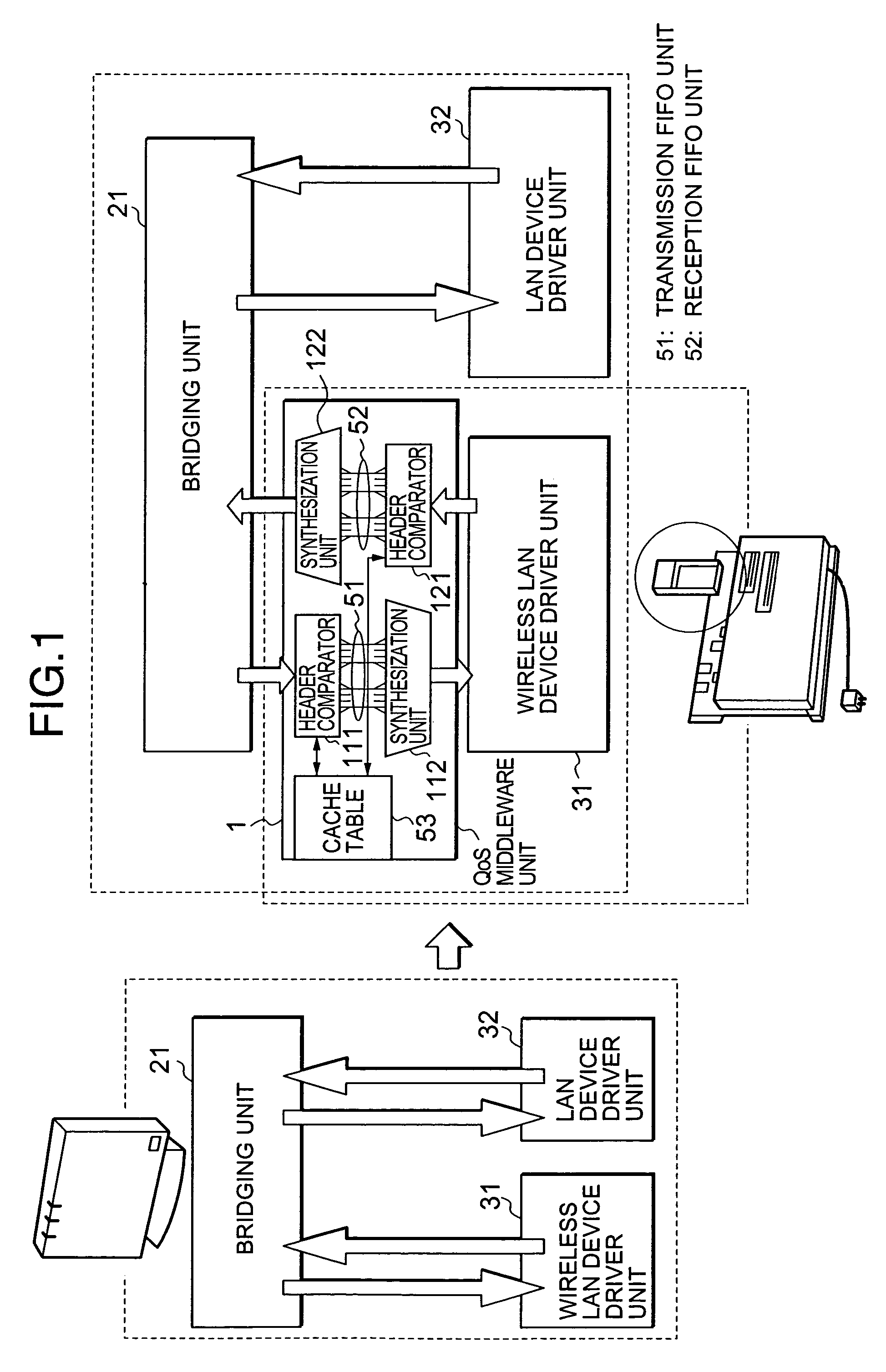
[0063]A bridge apparatus relays a wireless LAN 901, which conforms to IEEE 802.11 standards, and a wire LAN 902, which conforms to IEEE 802.3 standards.

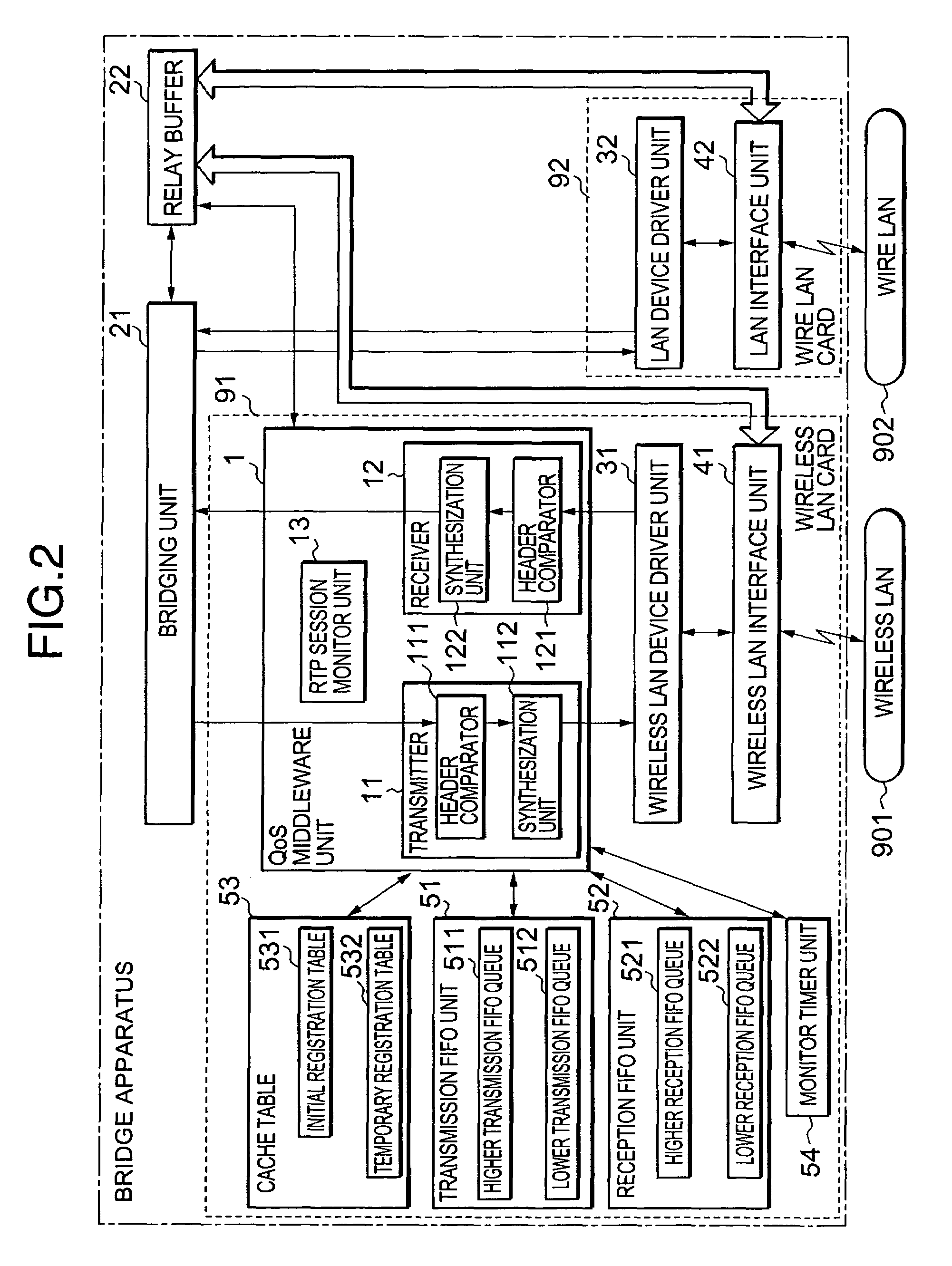
[0064]While referring to FIG. 2, the bridge apparatus comprises: a bridging unit 21, which uses an MAC address for relaying a frame packet; a wireless LAN card 91; a wire LAN card 92; and a relay buffer 22. To operate the bridging unit 21, in this embodiment a program is executed by a processor (not shown) mounted on the side of a main card that provides overall control for the bridge apparatus. While the bridge apparatus in FIG. 2 also includes other functional blocks and hardware units, for the sake of the explanation, these components are not shown.

[0065]In FIG. 2, the wireless LAN card 91 includes: a QoS middleware unit 1; a wireless LAN device driver unit 31, for exchanging data consonant with a communication protocol fo...


PUM


Abstract

Disclosed is a bridge apparatus for the relay of a frame between a wire LAN and a wireless LAN. When a frame transmitted by the wire LAN is a specific frame, a QoS middleware unit of the bridge apparatus adds a bridging request to an FIFO queue having a high priority. And when the frame received from the wire LAN is not a specific frame, the QoS middleware unit adds a bridging request to an FIFO queue having a low priority. A bridging unit performs the priority processing for the bridging request present in the FIFO queue having a high priority, and transmits the frame to the wireless LAN.

Description

BACKGROUND OF THE INVENTION[0001]1. Field of the Invention[0002]The present invention relates to a bridge apparatus and a bridge method, and relates in particular to a bridge apparatus and a bridge method for providing QoS (Quality of Service) between a device driver and a bridge.[0003]2. Description of the Related Prior Art[0004]A conventional, buffer employing bridge apparatus, for deployment between various network types, is disclosed in JP-A-5-22293, for example. According to the technique described in JP-A-5-22293, when a frame from a network A is transmitted to a reception buffer for a communication port A, a bridge processor reads the header in the frame received from the reception buffer, and performs a bridging process. Then, the bridge processor transmits the frame to the transmission buffer of a communication port B, and the communication port B transmits, to a network B, the frame in the transmission buffer.[0005]When, as described in JP-A-5-22293, a 100 Mbps LAN conform...

Claims


Application Information

Patent Timeline
Patent Type & Authority Patents(United States)
IPC IPC(8): H04L12/28H04L12/56H04L12/46H04L12/54H04L47/2416
CPCH04L12/4625H04L12/5693H04L47/14H04L47/2441H04L47/2416H04L47/2433H04L47/19H04L47/50H04W8/04
Inventor KOBAYASHI, YOSHIKAZU
Owner NEC CORP
Why Eureka
Try Eureka