In vivo planning and treatment of cancer therapy

a cancer therapy and in vivo technology, applied in the field of radiation-emitting devices, can solve the problems of difficult to guarantee the delivery of radiation to the treatment site, the actual amount of radiation inside the object is unknown, and the device cannot determine how much radiation has been deposited on the obj

Inactive Publication Date: 2008-03-18
SIEMENS MEDICAL SOLUTIONS USA INC
View PDF13 Cites 90 Cited by
  • Summary
  • Abstract
  • Description
  • Claims
  • Application Information

AI Technical Summary

Problems solved by technology

However, it is hard to guarantee the delivery of radiation to the treatment site.
However, the actual amount of radiation inside the object is unknown.
Unfortunately, these devices have no way of determining how much radiation has been deposited to

Method used


Image

  • In vivo planning and treatment of cancer therapy
  • In vivo planning and treatment of cancer therapy
  • In vivo planning and treatment of cancer therapy

Examples


Embodiment Construction

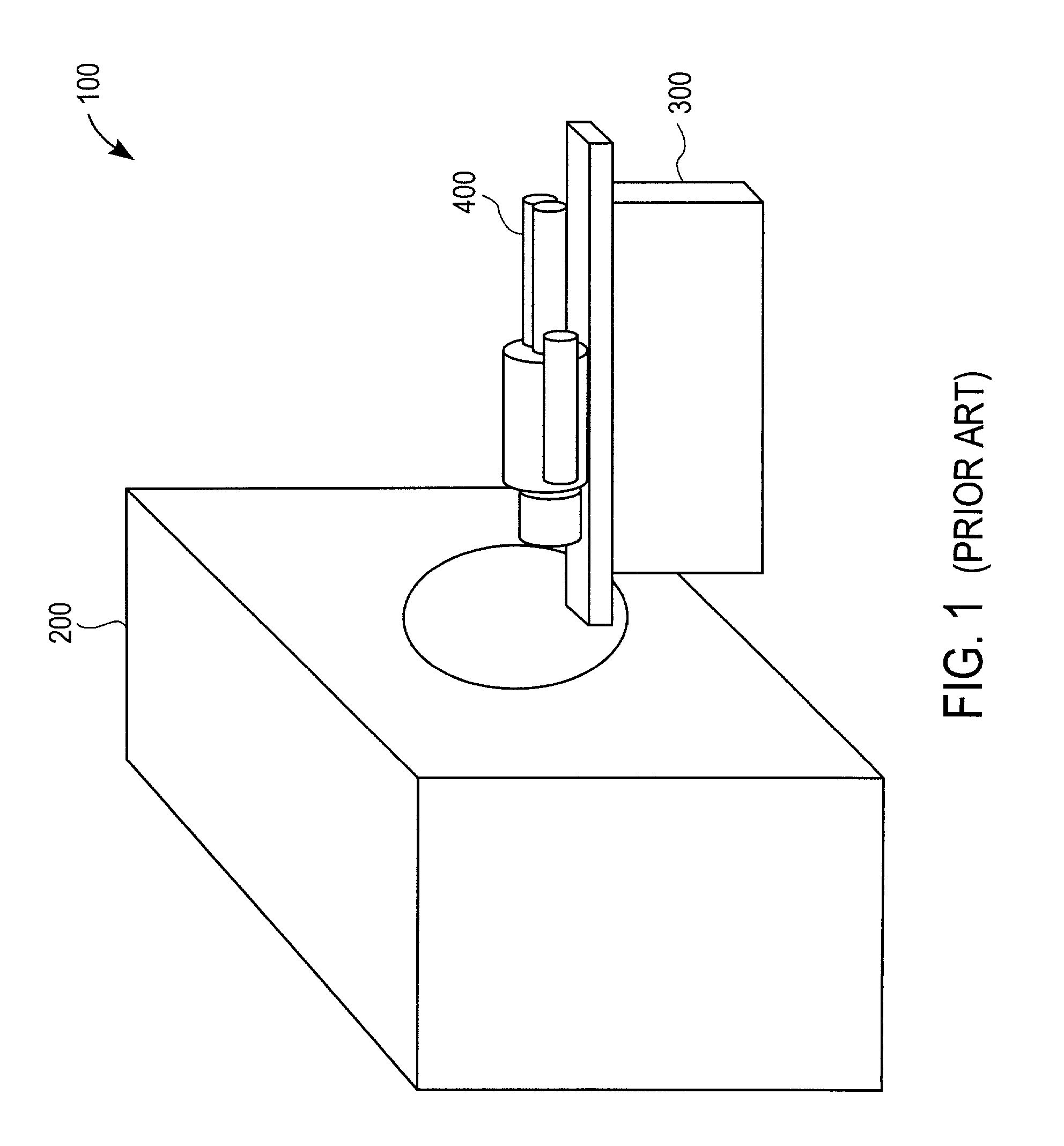
[0012]The following description is presented to enable one of ordinary skill in the art to make and use the invention. Descriptions of specific embodiments and applications are provided only as examples and various modifications will be readily apparent to those skilled in the art. The general principles described herein may be applied to other embodiments and applications without departing from the scope of the invention. Thus, the present invention is not to be limited to the embodiments shown, but is to be accorded the widest scope consistent with the principles and features described herein. For purpose of clarity, details relating to technical material that is known in the technical fields related to the invention have not been described in detail.

[0013]Turning now to the drawings, FIG. 1 illustrates computed tomography (“CT”) room 100 configured to acquire data in accordance with some embodiments of the present invention. CT room 100 includes CT device 200, CT table 300, and o...


PUM


Abstract

A system and method for delivering radiation to an object. A computer tomography machine generates CT data of the object. A radiation source with an output beam is directed to a predetermined irradiation field of the object. A detector above the object controls the output beam to the predetermined irradiation field of the object. A processor calculates the dose to the predetermined irradiation field of the object. Another detector below the object which measures the radiation delivered to the object.

Description

BACKGROUND OF THE INVENTIONDescription of the Related Art[0001]Radiation-emitting devices are generally known and used, for instance, as radiation therapy devices for the treatment of patients. A radiation therapy device generally comprises a gantry, which can be swiveled around a horizontal axis of rotation during the course of therapeutic treatment. A linear accelerator is located in the gantry for generating high-energy radiation beam (typically, of electrons or photons, that is, X-rays) for therapy. During treatment, this radiation beam is trained on a zone of a object located in the isocenter of the gantry rotation. Radiation treatment devices have built in safety schemes that give the user confidence that the correct radiation is being delivered. However, it is hard to guarantee the delivery of radiation to the treatment site.[0002]Before treatment, an object (e.g., a patient) may be scanned with a computer tomograph (CT), and / or treatment may be simulated with a diagnostic X-...

Claims


Application Information

Patent Timeline
IPC IPC(8): A61N5/10
CPCA61N5/1048A61N5/1042
Inventor HUGHES, JOHN H.CELI, JUAN CARLOSHERNANDEZ-GUERRA, FRANCISCO MIGUEL
Owner SIEMENS MEDICAL SOLUTIONS USA INC
Why Eureka
Try Eureka