Digital image enhancement using successive zoom images

a digital image and zoom image technology, applied in image enhancement, television systems, instruments, etc., can solve the problems of reducing the ability of a viewer to perceive, affecting the perception ability of viewers, and limiting the resolution of the sensors used

Inactive Publication Date: 2008-03-18
LOCKHEED MARTIN CORP
View PDF13 Cites 106 Cited by
  • Summary
  • Abstract
  • Description
  • Claims
  • Application Information

AI Technical Summary

Benefits of technology

[0020]The present invention is of a method for processing imagery using an Electro-Optical (EO) system, comprising: selecting a first frame of data as a template frame; capturing a second frame of data using the EO system; for a plurality of pixels of the second frame, correlating the plurality of pixels of the second frame with pixels of the template frame to generate a plurality of shift vectors, one for each pixel of the plurality of pixels of the second frame; registering the second frame with the template frame by interpolating the second frame using the plurality of shift vectors and re-sampling at least a portion of the second frame to produce a registered frame; re-sampling the template frame; and combining the re-sampled template frame and the registered frame to generate an averaged frame. In the preferred embodiment, re-sampling comprises electro

Problems solved by technology

In conventional EO systems, the sensors used are limited in their resolution by the fixed spacing between sensor elements.
A similar type of distortion can arise in, for example, a scene containing edge transitions which are so close together that a sensor cannot accurately resolve them.
Resultant distortion can manifest itself as color fringes, in a color camera, around an edge or the like, reducing the ability of a viewer to perceive, for example, letters or object outlines with clarity.
Range performance of an EO sensor is also often limited by the Nyquist frequency of the sensor, particularly those containing staring focal-plane arrays.
In addition, sensor range can be limited by distortion levels or noise associated with sensor construction.
These types of improvements, however, increase the cost and size of the system, which can lead to a design that is too costly or too large to fit the application.
However, dither mechanisms, such as a FSM, are usually very expensive and are sensitive to vibrations and alignment.
The base XR (extended range) technology as disclosed in U.S. patent a

Method used


Image

  • Digital image enhancement using successive zoom images
  • Digital image enhancement using successive zoom images
  • Digital image enhancement using successive zoom images

Examples


Embodiment Construction

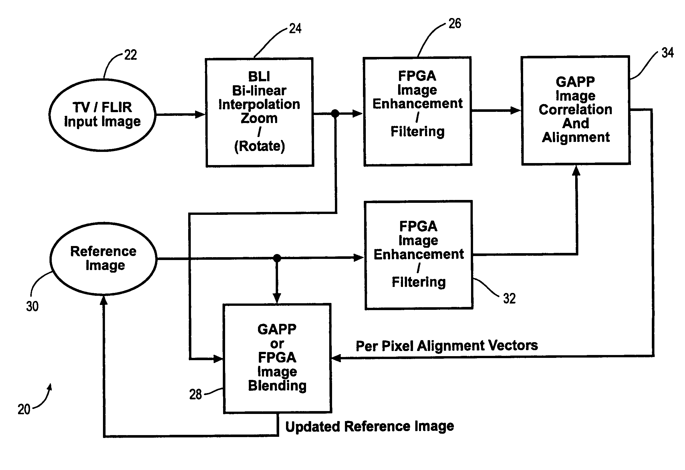
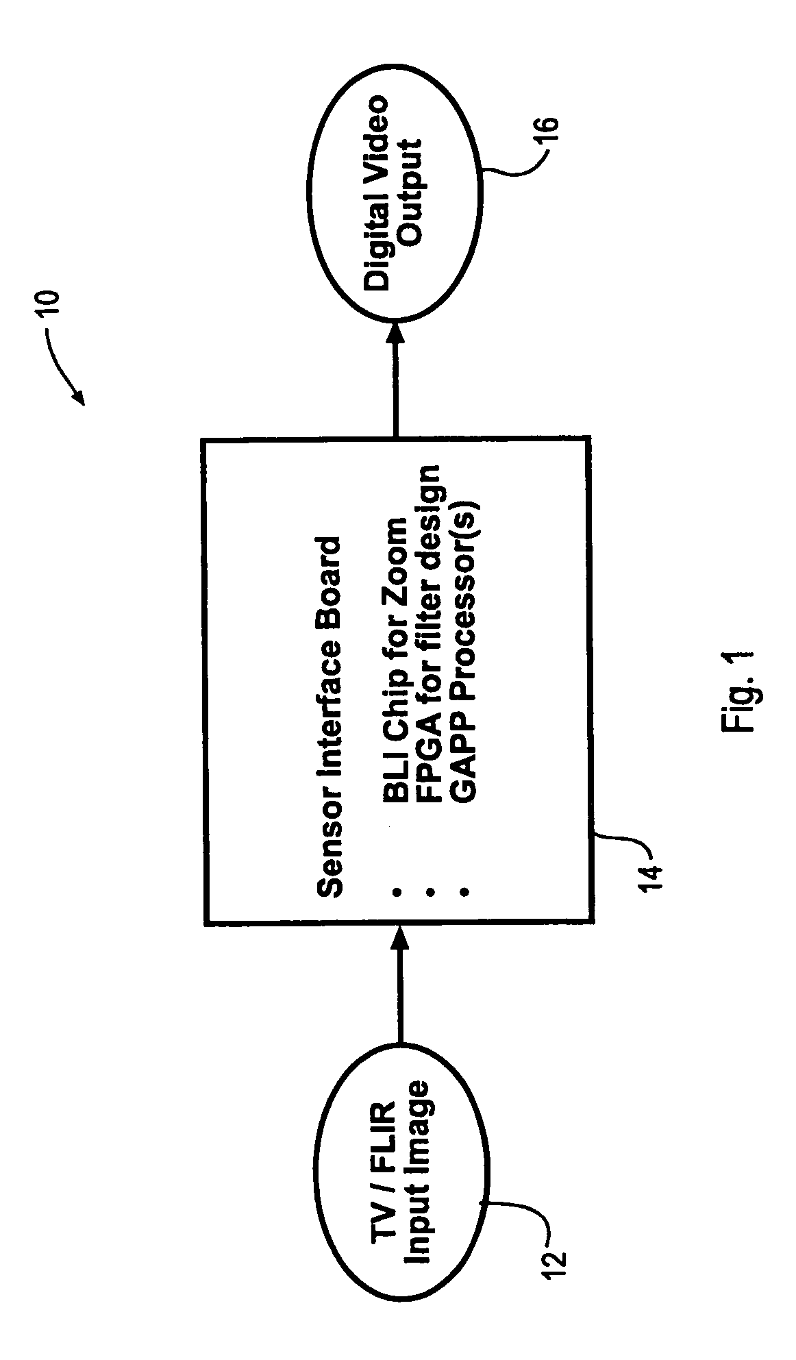
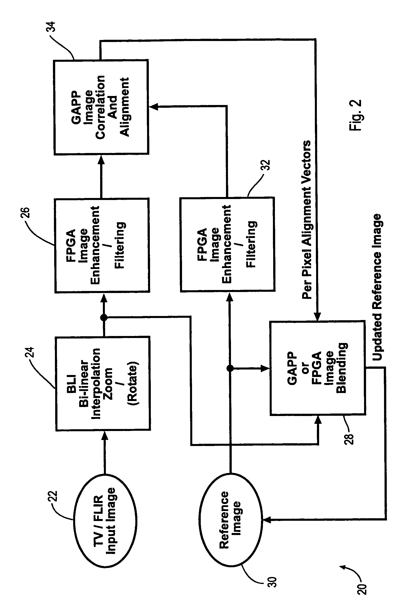
[0027]The present invention is of a system and method for enhancing digital images, particularly those acquired by EO systems. The invention dedicates a separate correlation tracking algorithm to each pixel within the desired output image. Using this technique, each pixel receives individual motion compensation based on matching the local neighborhood between the reference frame and the input image. The invention provides a larger coverage area than with existing technology, thereby providing enhanced imagery for any application, particularly for target detection. The invention also provides per-pixel motion compensation, with concomitant higher quality images, particularly in scenarios where the current XR technology would have difficulty.

[0028]The invention preferably performs a per-pixel registration of electronically zoomed successive video frames to provide enhanced image fidelity. Electronic zoom normally just creates pseudo-data between pixels; however, by temporally blending...


PUM


Abstract

A method and Electro-Optical (EO) system for processing imagery comprising selecting a first frame of data as a template frame; capturing a second frame of data using the EO system, for a plurality of pixels of the second frame, correlating the plurality of pixels of the second frame with pixels of the template frame to generate a plurality of shift vectors, one for each pixel of the plurality of pixels of the second frame, registering the second frame with the template frame by interpolating the second frame using the plurality of shift vectors and re-sampling at least a portion of the second frame to produce a registered frame, re-sampling the template frame, and combining the re-sampled template frame and the registered frame to generate an averaged frame.

Description

CROSS-REFERENCE TO RELATED APPLICATIONS[0001]The present application is a continuation-in-part application of the following applications: (1) U.S. patent application Ser. No. 09 / 840,920, entitled “Scene-based non-uniformity correction for detector arrays”, filed Apr. 25, 2001, and published as Publication No. 2002 / 0159101 on Oct. 31, 2002; (2) U.S. patent application Ser. No. 09 / 841,081, entitled “Dynamic range compression”, filed Apr. 25, 2001, and published as Publication No. 2002 / 0159648 on Oct. 31, 2002; (3) U.S. patent application Ser. No. 09 / 841,079, entitled “Extended range image processing for electro-optical systems”, filed Apr. 25, 2001, and published as Publication No. 2002 / 0159651 on Oct. 31, 2002; and (4) U.S. patent application Ser. No. 10 / 125,348, entitled “Scene-based non-uniformity offset correction for staring arrays”, filed Apr. 19, 2002, and published as Publication No. 2003 / 0198400 on Oct. 23, 2003, and the specifications thereof are incorporated herein by refer...

Claims


Application Information

Patent Timeline
IPC IPC(8): G06K9/00G06K9/62G06K9/72H04N5/228H04N7/12G06V20/13
CPCG06K9/0063G06T5/50G06T7/0026G06T2207/10016G06T2207/10048G06T7/32G06V20/13
Inventor GOLD, JR., V. EDWARD
Owner LOCKHEED MARTIN CORP
Why Eureka
Try Eureka