Impedance mismatch modeling in a data flow or discrete time based system simulation

a data flow and discrete time based system technology, applied in the field of eda tools for integrated circuit design, can solve the problems of large number of additional connections, and difficulty in establishing system schematics or netlists

Active Publication Date: 2008-03-18
AWR CORP
View PDF3 Cites 11 Cited by
  • Summary
  • Abstract
  • Description
  • Claims
  • Application Information

AI Technical Summary

Problems solved by technology

This approach has several problems.
The first is that the extra terminal connections would greatly complicate the setup of the system schematic or netlist.
A more severe problem is that each model could only pass information that it knew about at the time the model was implemented.
The additional possible connections could become quite large.
This assumption can lead to very significant modeling errors in the simulated results.
In general, termination impedances are complex frequency dependent functions that result in frequency dependent mismatch losses between the blocks.
The usual assumption that all blocks are ideally terminated can lead to very significant modeling errors in the simulated results.
In general, termination impedances are complex frequency dependent functions that result in frequency dependent mismatch losses between the blocks.

Method used


Image

  • Impedance mismatch modeling in a data flow or discrete time based system simulation
  • Impedance mismatch modeling in a data flow or discrete time based system simulation
  • Impedance mismatch modeling in a data flow or discrete time based system simulation

Examples


Embodiment Construction

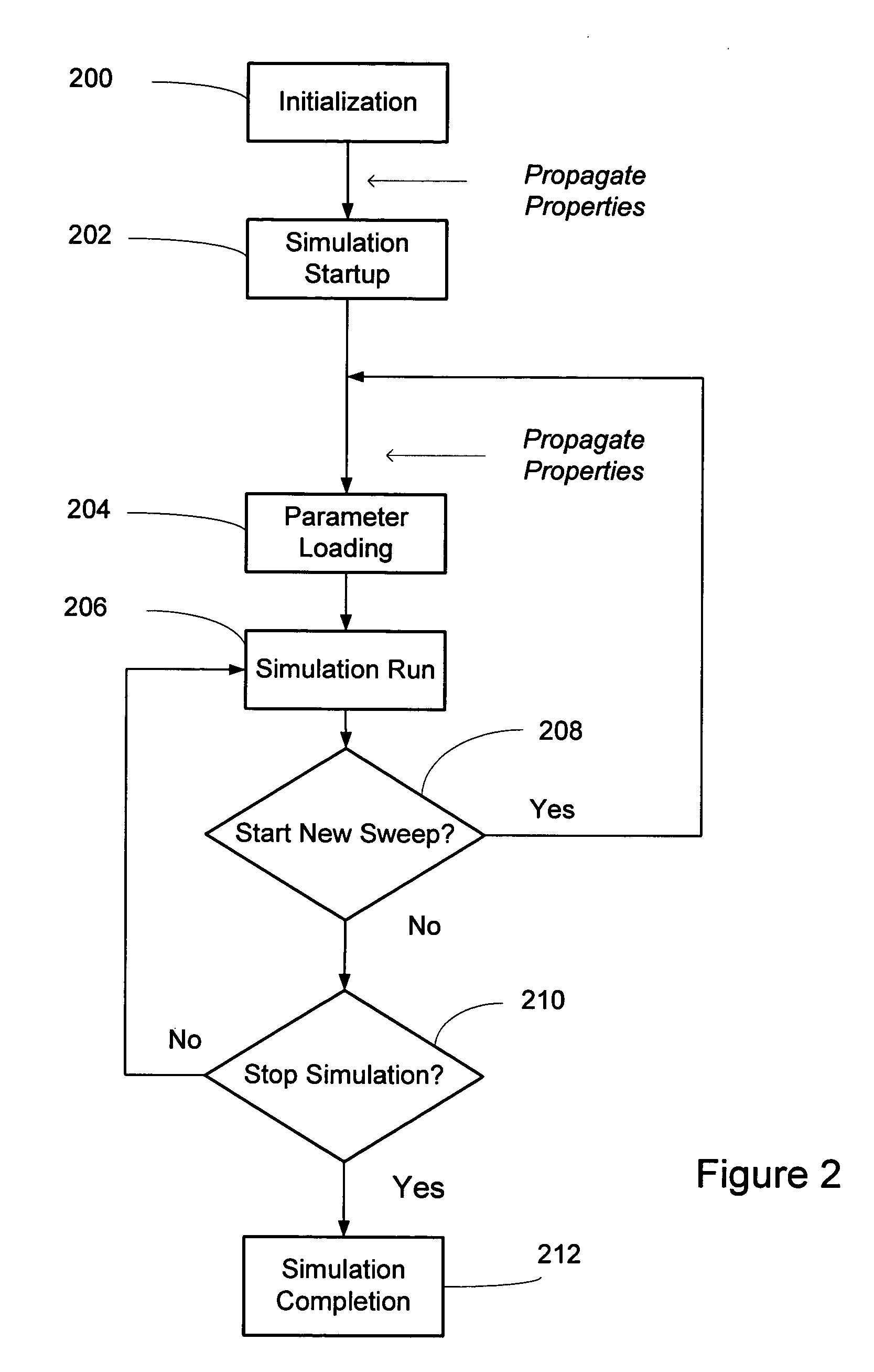
[0056]The invention provides for the propagation of the signal information as well as additional information, from one block to the next in a system. This propagation of information in addition to the signal information uses the connectivity of the blocks to propagate certain system or block properties from one block to the next block. A “property” is well known to one skilled in the art. It may be composed of an identifier and a value, where the identifier may be a string, or a numeric value, including pointers, used to uniquely identify the property. The value of the property is the information represented by the property and may come in many different formats, such as a numeric value, a vector of numeric values, text, or a data structure. A typical property may be represented as a name value pair (could be other representations), where the value may be any type of information describing or a characteristic associated with the block. Examples may include another name, a number, a ...


PUM


Abstract

This invention provides directional connectivity described by the interconnections of the blocks in the schematic or netlist that are used to propagate impedance data from one block to another. The propagation of impedance data for discrete time based simulation programs allow for the simulation under less than ideal termination conditions between the blocks. This invention also supports functionality where the input impedance and output impedance of each block are not perfectly terminated. This assumption can lead to very significant modeling errors in the simulated results. In general, termination impedances are complex frequency dependent functions that result in frequency dependent mismatch losses between the blocks. This invention allows for the propagation and calculation of impedance mismatches between the various blocks.

Description

CROSS REFERENCE TO RELATED APPLICATIONS[0001]This patent application claims priority to U.S. Provisional Patent Application No. 60 / 392,647 filed on Jun. 29, 2002 and is incorporated by reference.BACKGROUND OF THE INVENTION[0002]1. Field of the Invention[0003]This invention provides electronic design automation (“EDA”) tools for integrated circuit design. Specifically, this invention provides for impedance mismatch of a behavior model during circuit simulation.[0004]2. Related Art[0005]A digital communications link might be modeled according to FIG. 1. In this model, a digital source 100 is coupled to a channel encoder 102. A modulator 104 receives the signal from the channel encoder 102 and transmits the signal across the channel 106. On the receiving end, the demodulator 108 demodulates the received signal and the channel decoder 110 decodes the signal to produce the received data 112. The channel encoder 102 is matched with the channel decoder 112, and the modulator 104 is matched...

Claims


Application Information

Patent Timeline
Patent Type & Authority Patents(United States)
IPC IPC(8): G06F17/50H01Q11/12H03K17/16H04B1/10
CPCG06F17/5036G06F30/367
Inventor PEKAREK, JOSEPH EDWARDSANTOS, ALBERTHUDSON, SCOTTY
Owner AWR CORP
Why Eureka
Try Eureka