Optical connector

a technology of optical connectors and connectors, applied in the field of optical connectors, can solve the problems of inconvenient operation, loss of propagated light, and further increase of bending of optical fibers (coated optical fibers) to achieve the effect of eliminating the inconvenience of propagated light loss

Active Publication Date: 2008-03-25
FUJIKURA LTD +1
View PDF7 Cites 45 Cited by
  • Summary
  • Abstract
  • Description
  • Claims
  • Application Information

AI Technical Summary

Benefits of technology

[0008]In consideration of the problems described above, an object of the present invention is to provide an optical connector that is structured such that the bending of the bent insertion optical fiber is decreased due to reliably abutting the back end of the inner optical fiber and the distal end of the optical fiber, and wherein the inconvenience of loss occurring in the propagated light is eliminated, and light is advantageously propagated.
[0012]A third aspect of the present invention is characterized in that, in the optical connector of the sixteenth aspect, a retraction restricting convexity, which restricts the movement of the anchoring member in the retraction direction by abutting the back end side wall space of the anchoring member when the cover body is positioned at the holding position, is provided so as to project on the back end portion of the cover body.
[0013]A fourth aspect of the present invention is characterized in that, in the optical connector of the sixteenth aspect, a projecting portion that projects in the transverse direction is provided on the anchoring member. An engaging window portion passes through the cover body in the transverse direction. When the cover body is positioned in the holding position, the projecting portion of the anchoring member allows play, and can thereby engage the engaging window portion.
[0016]According to the optical connector of the present invention, the bending of the insertion optical fiber that is bent because of the reliable abutment between the back end of the inner optical fiber and the distal end of the insertion optical fiber is decreased, and the inconvenience in which loss occurs in the propagated light is eliminated. Thereby, in the optical connector, the inner optical fiber and the insertion optical fiber are properly connected, and light is advantageously propagated.

Problems solved by technology

However, when the insertion optical fiber is attached to the optical fiber after bending in the manner described above, the following inconveniences occur.
In addition, when the optical fiber is bent, at the bending location, loss may occur in the propagated light.
Thereby, the bending of the optical fiber (coated optical fiber) is further increased, and the inconveniences described above become severe.

Method used


Image

  • Optical connector
  • Optical connector
  • Optical connector

Examples


Embodiment Construction

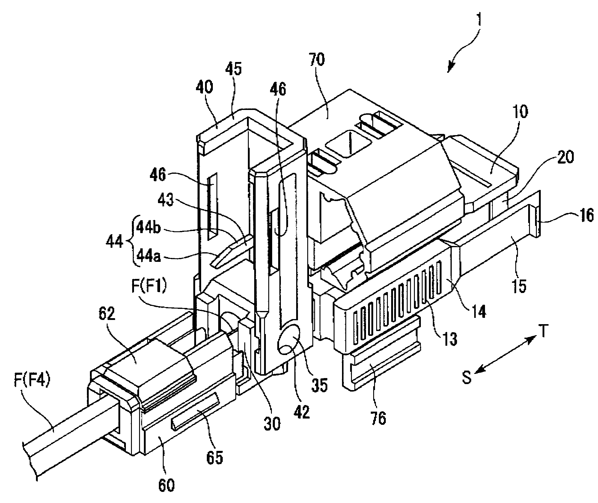
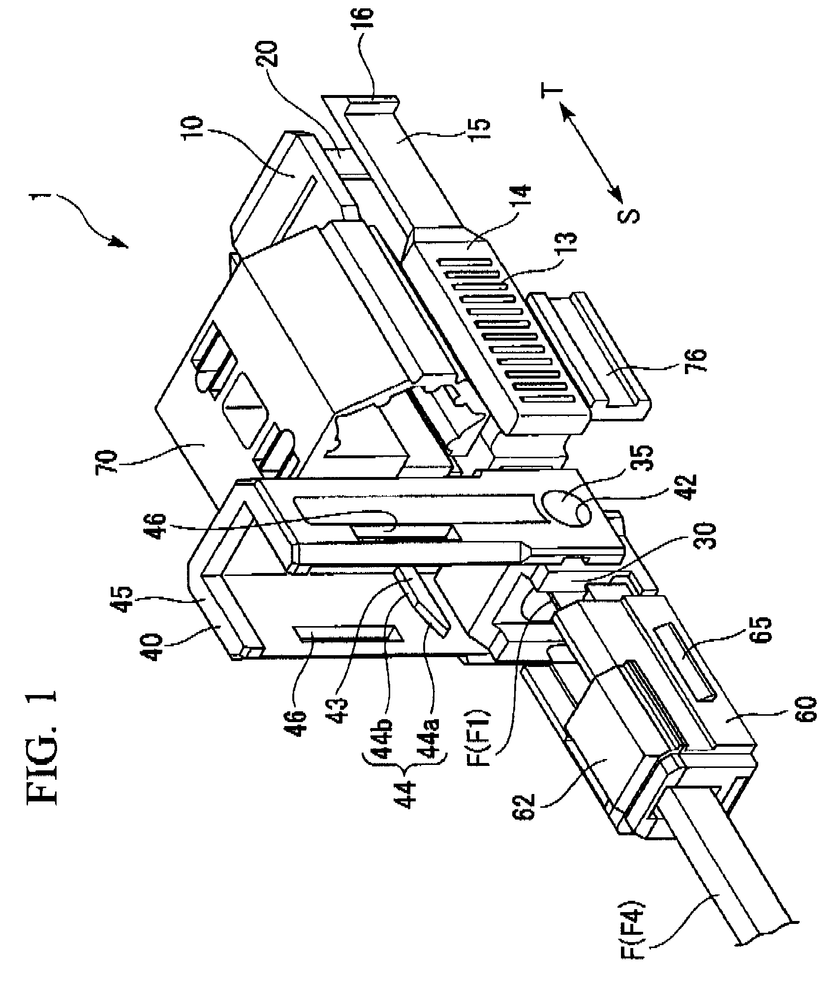
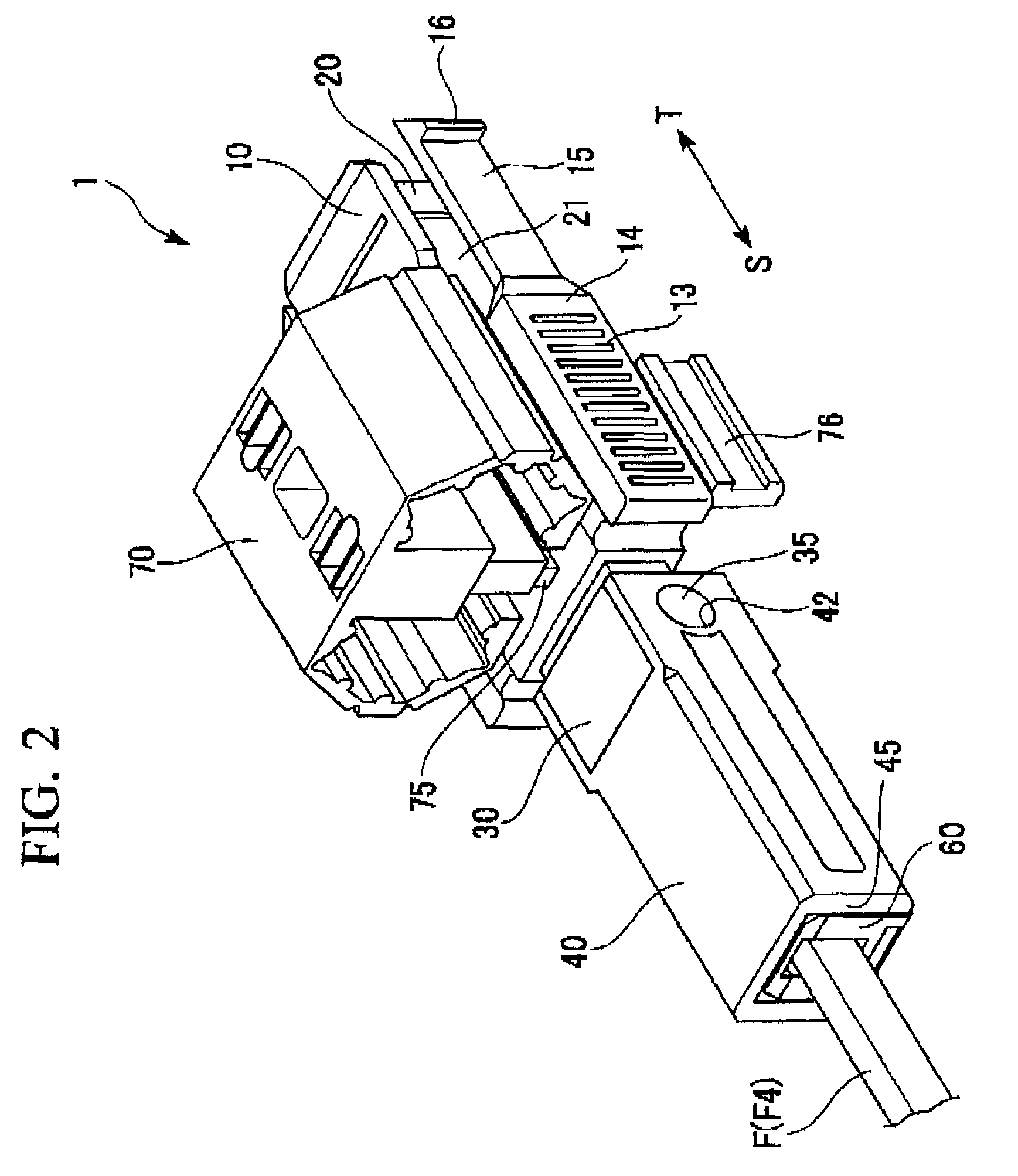
[0031]Hereafter, an embodiment of the present invention will be explained with reference to the drawings. FIG. 1 is a perspective view of the entire optical connector (where the cover body is in the stand-by position) according to the present invention. FIG. 2 is a perspective view of the entire optical connector (where the cover body is in the holding position) according to the present invention FIG. 3 is a horizontal cross-sectional drawing of the optical connector in FIG. 1. FIG. 4 is a vertical cross-sectional drawing (where the outer cover is in the stand-by position) of the optical connector in FIG. 1. FIG. 5 is a vertical cross-sectional drawing (where the outer cover is in the holding position) of the optical connector of FIG. 1. FIG. 6A is a plan view of the connector, and FIG. 6B is a side view of the connector. FIG. 7 is a perspective view of the connector body. FIG. 8A and FIG. 8B are perspective views of the clamping member. FIG. 9A is a perspective view and a cut-away ...


PUM


Abstract

An optical connector includes a connector body that has a first optical fiber housed in advance in a ferrule so as to project from a back end of the ferrule opposite to the connecting end surface and an anchoring fixture that anchors a second optical fiber that is to be optically connected to the first optical fiber, and by pressing the anchoring fixture into the connector body while the second optical fiber is anchored in this anchoring fixture, the anchoring fixture and the connector body are connected to optically connect the first optical fiber and the second optical fiber, and the connecting portion that connects the anchoring fixture and the connector body form a movable connecting portion that is adapted to vary the direction of the anchoring fixture with respect to the connector body.

Description

BACKGROUND OF THE INVENTION[0001]1. Field of the Invention[0002]The present invention relates to an optical connector used in the connection of optical fibers.[0003]Priority is claimed on Japanese Patent Application No. 2006-62913, filed Mar. 8, 2006, the content of which is incorporated herein by reference.[0004]2. Description of Related Art[0005]In recent years, an optical connector has been propose, of which assembling operation can be carried out at a connection site other than a factory. For such an optical connector, an optical connector including a ferrule that houses and fastens an optical fiber in advance after the distal end surface thereof has been polished and a clamping portion disposed on the back portion (the position on the side opposite to the distal end surface) of this ferrule has been proposed. In this optical connector, in the clamping portion the optical fiber (below, the inner optical fiber) on the ferrule side and another connection optical fiber (below, the ...

Claims


Application Information

Patent Timeline
Patent Type & Authority Patents(United States)
IPC IPC(8): G02B6/36
CPCG02B6/3846G02B6/3887G02B6/3806G02B6/381G02B6/3888
Inventor SAITO, DAIGOTAKIZAWA, KAZUHIROFURUKAWA, HIROSHIKOBAYASHI, TERUTAKEAOYAMA, HIROSHIHOSHINO, YASUHIKOODA, YASOU
Owner FUJIKURA LTD
Why Eureka
Try Eureka