Hydraulically assisted tubing expansion

a technology of hydro-assisted tubing and diametric expansion, which is applied in the direction of drilling pipes, drilling rods, borehole/well accessories, etc., can solve the problems of requiring significant force to the cone, difficult to predict, and involve a degree of uncertainty, so as to reduce the thickness of the wall, reduce the thickness of the tubing, and achieve the effect of localising the compressive yield

Inactive Publication Date: 2008-04-01
WEATHERFORD TECH HLDG LLC
View PDF45 Cites 19 Cited by
  • Summary
  • Abstract
  • Description
  • Claims
  • Application Information

AI Technical Summary

Benefits of technology

[0014]Alternatively, or in addition, the fluid pressure internally of the tubing may be maintained at a relatively high level by providing a relatively high density fluid internally of the tubing. This feature may be utilised in other forms of tubing expansion, not reliant on a varying pressure. In particular, the use of a high density fluid will provide a relatively high hydrostatic pressure, reducing or even eliminating the need to utilise pumps to provide the desired fluid pressure in the bore. The elevated fluid pressure achieved by providing a column of high density fluid may in addition, or alternatively, be utilised for other purposes, such as driving an expansion cone or other tool through the tubing.
[0044]The expansion device may define a fixed diameter, or a variable diameter. The device may be compliant, that is the device has a degree of flexibility to permit the device to, for example, negotiate sections of the tubing which cannot be expanded to a desired larger diameter or form. Alternatively, the expansion device may define a fixed diameter and be non-compliant. In certain embodiments, the expansion device may feature both fixed and compliant elements.

Problems solved by technology

One difficulty that has been experienced with cone expansion is the requirement to apply significant forces to the cone to drive the cone through the tubing.
The sole use of fluid pressure to expand tubing, rather than mechanical expansion techniques utilising cones or other devices, is perceived to involve a degree of uncertainty, as it is difficult to predict how a particular tubular will expand in response to an internal fluid pressure which creates a force above the yield strength of the tubular.
In particular, a point or area of relative weakness in the tubing wall may result in the tubing bursting or expanding in a non-uniform manner.

Method used


Image

  • Hydraulically assisted tubing expansion
  • Hydraulically assisted tubing expansion
  • Hydraulically assisted tubing expansion

Examples


Embodiment Construction

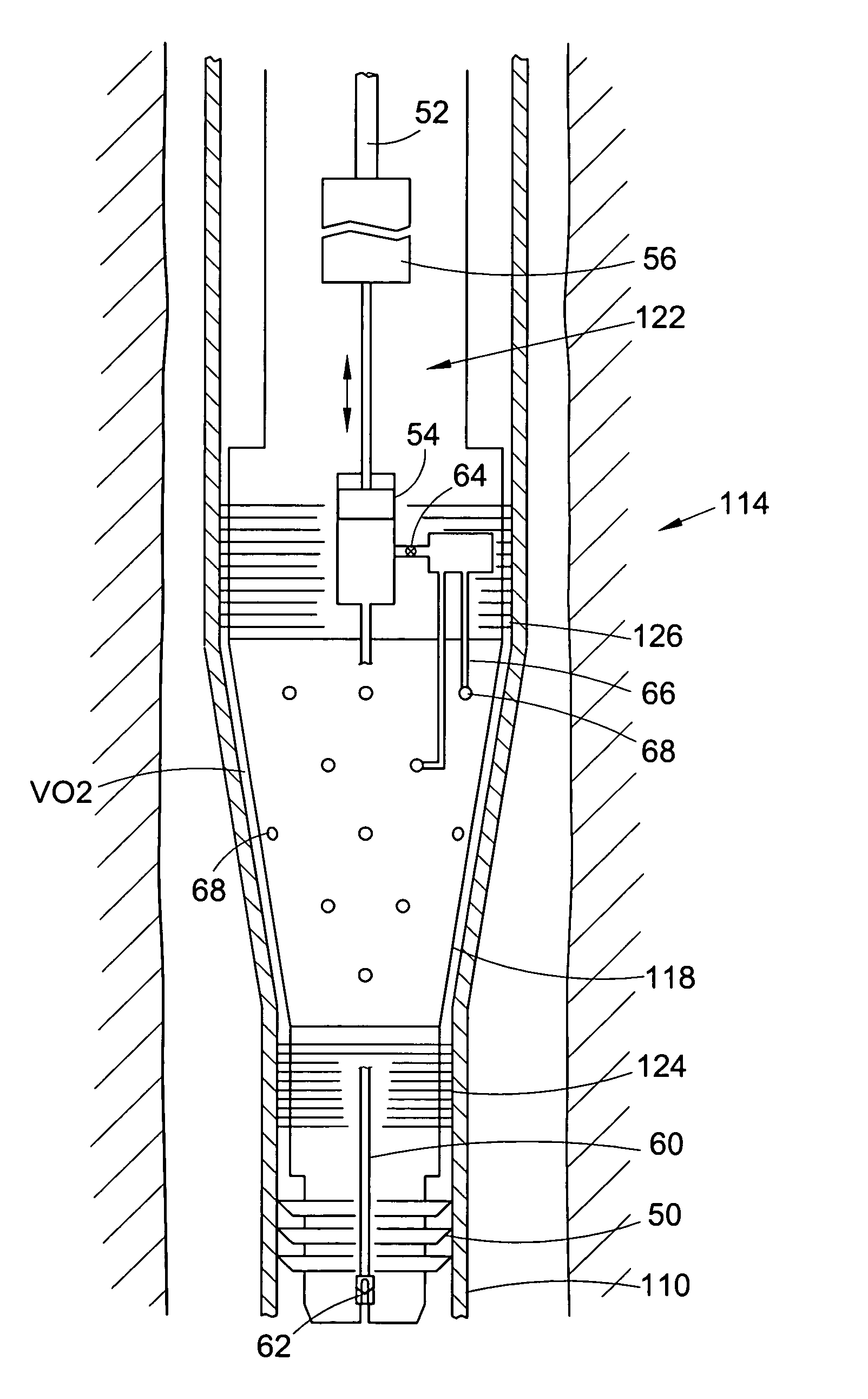
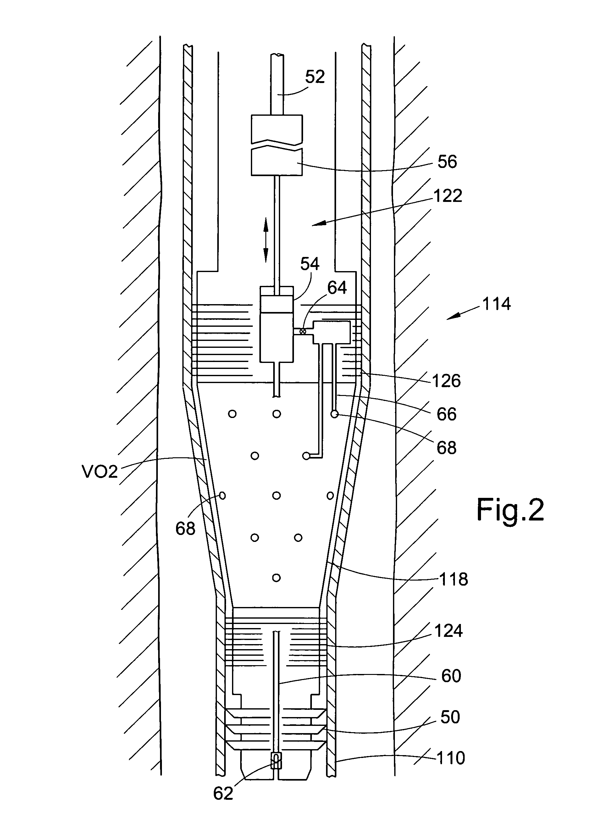
[0048]FIG. 1 of the drawings illustrates a tubing in the form of a bore lining casing 10 located in a drilled bore 12, such as may be utilised to gain access to a subterranean hydrocarbon reservoir. The casing 10 is run into the bore 12 in a smaller diameter first condition, of diameter D1, and is subsequently expanded to a larger second diameter D2.

[0049]Expansion of the casing 10 is achieved using expansion apparatus 14 mounted on the lower end of a string of drill pipe 16, which extends to surface. The expansion apparatus 14 comprises a semi-compliant expansion cone 18, that is a cone of relatively hard material which defines an outer expansion surface 20 and which defines a maximum expansion diameter corresponding to the expanded tubing diameter D2. However, the cone 18 is arranged such that the expansion surface may be deflected radially inwardly to a limited extent to accommodate situations where, for example, the casing 10 cannot be expanded to the diameter D2. A variable vol...


PUM

PropertyMeasurementUnit
cone angleaaaaaaaaaa
specific gravityaaaaaaaaaa
cone angleaaaaaaaaaa

Abstract

A method of expanding tubing comprises applying a varying fluid pressure across the wall of the tubing. The variation in pressure may be achieved by varying one or both of the fluid pressure within the tubing and the fluid pressure externally of the tubing. A body of varying volume may be located in a volume of fluid associated with the tubing. Alternatively, the volume of a body of fluid associated with the tubing may be varied by movement of a wall portion defining a boundary of the volume, which wall portion may be associated with an oscillator or a percussive or hammer device. In other embodiments a pressurised fluid source may be provided, and the fluid may be supplied at varying pressure from the source. An increase in pressure within the tubing may be accompanied by a reduction in pressure externally of the tubing.

Description

CROSS-REFERENCE TO RELATED APPLICATIONS[0001]This application claims benefit of Great Britain patent application serial number GB 0306774.1, filed Mar. 25, 2003, which is herein incorporated by reference, this application is a continuation-in-part of U.S. patent application Ser. No. 10 / 805,914, filed Mar. 22, 2004 now U.S. Pat. No. 6,976,536, which is a continuation of U.S. patent application Ser. No. 10 / 114,923, filed Apr. 3, 2002, now U.S. Pat. No. 6,712,151, which claims benefit of Great Britain patent application Serial No. 0108638.8, filed Apr. 6, 2001, and this application is a continuation-in-part of U.S. patent application Ser. No. 10 / 787,993, filed Feb. 26, 2004, which claims benefit of Great Britain patent application Serial No. 0304335.3, filed Feb. 26, 2003.BACKGROUND OF THE INVENTION[0002]1. Field of the Invention[0003]This invention relates to hydraulically assisted tubing expansion. In particular, but not exclusively, the invention relates to hydraulically assisted di...

Claims


Application Information

Patent Timeline
Patent Type & Authority Patents(United States)
IPC IPC(8): E21B23/00B21D26/02B21D31/04B21D39/20E21B43/10
CPCB21D26/033B21D31/04B21D39/20E21B43/105
Inventor SIMPSON, NEIL ANDREW ABERCROMBIERUDD, WAYNE
Owner WEATHERFORD TECH HLDG LLC
Why Eureka
Try Eureka