
Suspension

a suspension and trailing arm technology, applied in the field of suspensions, can solve the problems of affecting the ride quality of the vehicle and not providing satisfactory performance, and achieve the effect of eliminating or substantially reducing ride height errors

Inactive Publication Date: 2008-04-01
VOLVO TRUCKS NORTH AMERICA
View PDF46 Cites 11 Cited by
  • Summary
  • Abstract
  • Description
  • Claims
  • Application Information

AI Technical Summary

Benefits of technology

This configuration significantly lowers the pivot axis, improving suspension performance by reducing drive line vibrations, enhancing traction, and maintaining precise ride height control, especially during vehicle curvature.

Problems solved by technology

The distance of the pivot axis above ground level can affect the ride quality of the vehicle.
However, simply elongating an existing hanger bracket design in order to lower the trailing arm pivot axis, does not provide satisfactory performance.

Method used


Image

  • Suspension
  • Suspension
  • Suspension

Examples


Embodiment Construction

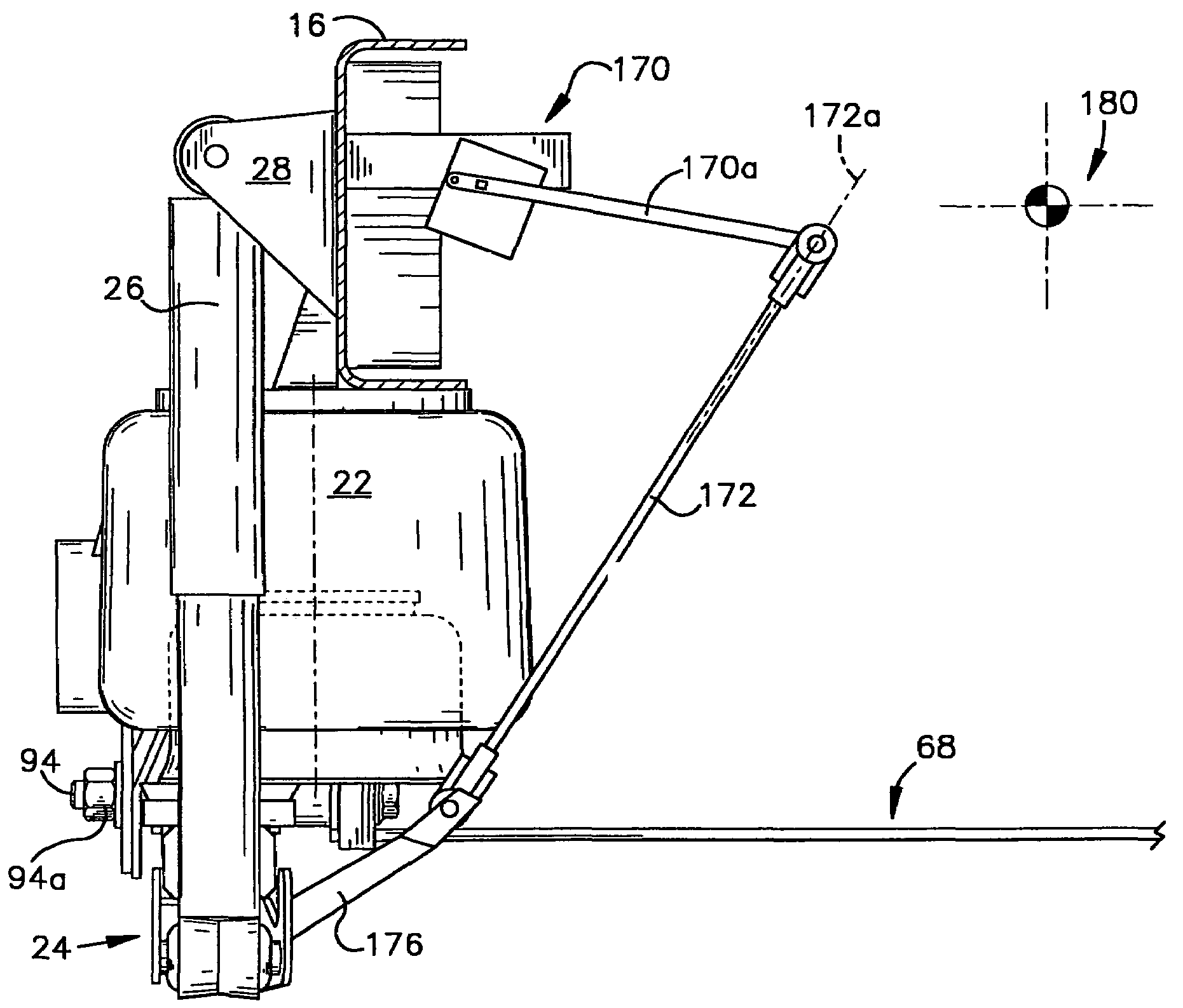
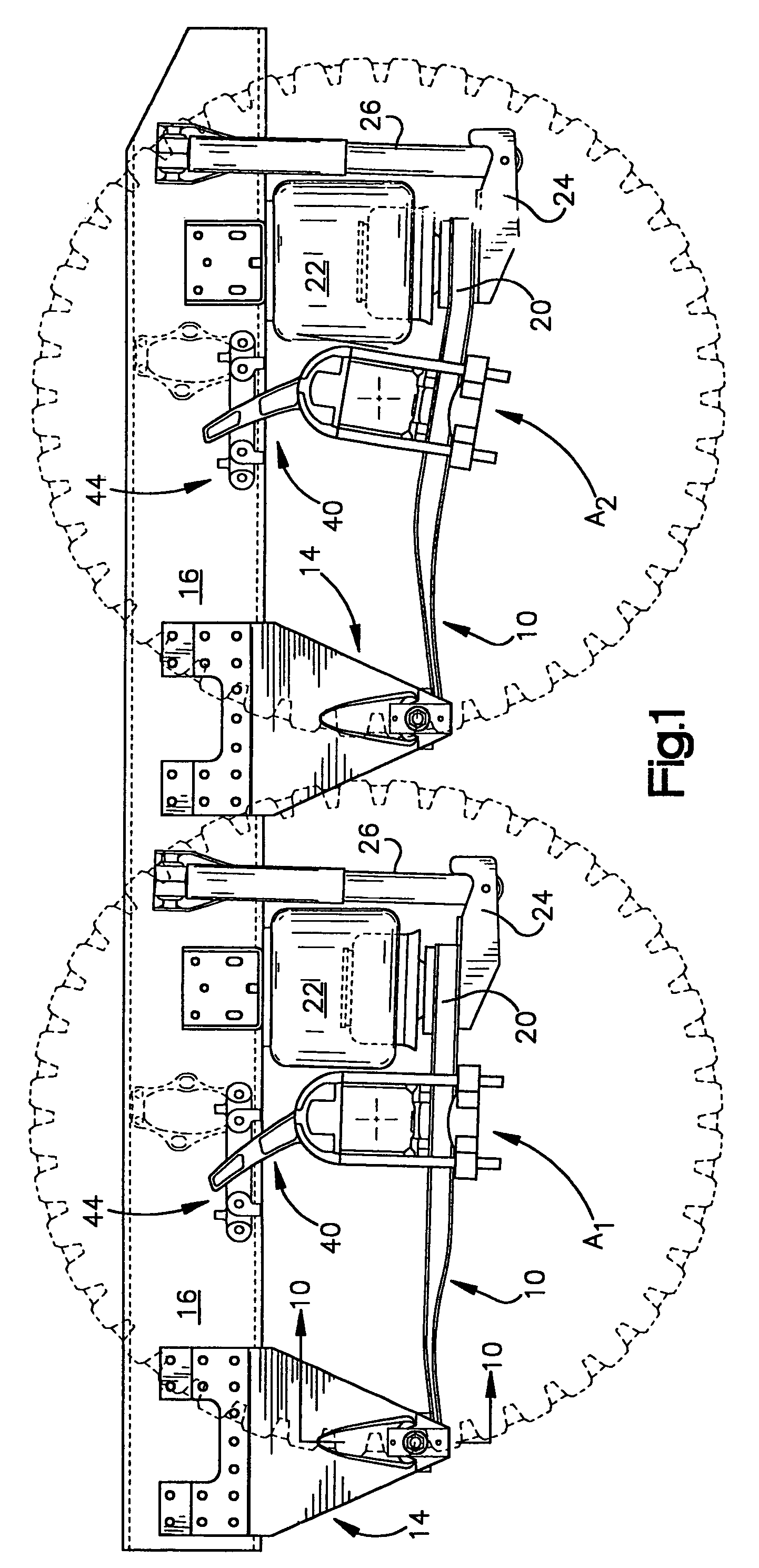
[0024]FIG. 1 illustrates a rear suspension of a tractor unit of a highway truck constructed in accordance with the preferred embodiment of the invention. The illustrated suspension is intended for use with a tractor unit having dual rear axles, indicated generally by the reference characters A1, A2. However, the invention can be used with a tractor unit having a single rear axle.

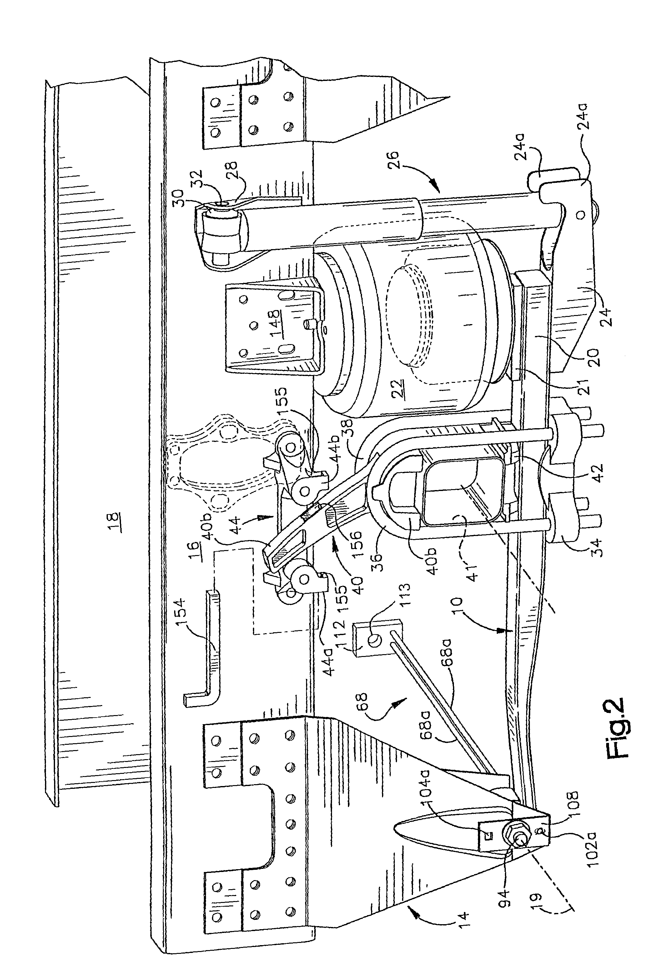
[0025]For purposes of explanation, the suspension components for the leading rear axle A1 will be described and are illustrated in FIG. 2. It should be understood, however, that the inventive features can be used on either or both of the rear axle suspensions.

[0026]The suspension illustrated in FIG. 2 is best characterized as a trailing arm, pneumatic or air suspension. In particular, the suspension includes a trailing arm 10, the forward end of which is held by a trailing arm hanger bracket 14. As seen best in FIG. 2, the hanger bracket 14 is mounted to and depends downwardly from the side of a frame rail o...


PUM


Abstract

A rear axle suspension for a highway truck that includes a pair of trailing arms suspended below a frame by a pair of hanger brackets. The hanger brackets define a pivot axis for the trailing arms. A supplemental axle locating member is attached to the axle and includes an extension member that is engageable with a bracket held by the frame. The hanger brackets are laterally compliant and each comprise an inner and outer plate, one of which is bent outwardly to define a gap within which an associated trailing arm is mounted. A moment canceling member extends between the hanger brackets and resists outward bending of the brackets. A height control valve is operated by an operating rod having an axis that passes through, or in close proximity, to the roll center of the vehicle in order to reduce ride height errors.

Description

TECHNICAL FIELD[0001]The present application relates generally to suspensions and, in particular, to a rear, trailing arm type suspension.BACKGROUND ART[0002]Many vehicles such as highway trucks include trailing arm type suspensions which support a rear axle and define its path of movement with respect to the vehicle frame. In some current highway truck designs, each trailing arm is constructed of spring steel and may comprise one or more “leaves.” The term “leaves” is used because at least some of the trailing arms being used by truck manufacturers are being made by leaf spring manufacturers from materials and in configurations that are or were used in “leaf” springs. In conventional designs of this type of suspensions, outboard ends of the axle are secured to respective trailing arms and, in effect, the arms support and locate the axle with respect to the vehicle frame.[0003]In some current suspension designs, the leading end of the trailing arm is suspended below its associated f...

Claims


Application Information

Patent Timeline
Patent Type & Authority Patents(United States)
IPC IPC(8): B60G11/46B60G1/00B60G7/00B60G7/02B60G9/00B60G9/04B60G11/113B60G11/12B60G11/27B60G17/005
CPCB60G7/02B60G9/003B60G11/113B60G11/12B60G11/465B60G17/005B60G2200/31B60G2202/112B60G2202/134B60G2202/152B60G2204/121B60G2204/129B60G2204/143B60G2204/148B60G2204/43B60G2204/4306B60G2204/44B60G2204/45B60G2204/4604B60G2206/601B60G2206/722B60G2300/0262
Inventor SVARTZ, BJORN O.WHITE, DARRIS L.
Owner VOLVO TRUCKS NORTH AMERICA
Learn More