Shallow angle needle guide apparatus and method

a needle guide and needle technology, applied in applications, ultrasonic/sonic/infrasonic image/data processing, ultrasonic/sonic/infrasonic diagnostics, etc., can solve the problem of rotatable needle within the guide, and achieve the effect of facilitating the insertion of the needle into the patien

Inactive Publication Date: 2008-04-01
CIVCO MEDICAL INSTR CO
View PDF17 Cites 69 Cited by
  • Summary
  • Abstract
  • Description
  • Claims
  • Application Information

AI Technical Summary

Benefits of technology

[0005]The present invention is directed to a needle guide for controlling the direction of a needle as it enters a patient during imaging analysis and permitting a needle to be directed into a shallow target. The needle guide typically includes a curved path that permits a needle to enter into the needle guide at a first angle and then exit the needle guide at a different second angle near the surface of a patient. Typically the needle can enter the needle guide at an angle more obtuse to the surface of the patient than where it exits the needle guide. In this manner insertion of a needle into a patient is facilitated because the needle guide allows shallow needle placements, including needle placements that enter the skin at an angle approaching or parallel to the skin surface.

Problems solved by technology

Also, in some implementations the needle remains rotatable within the guide even when within the channel.

Method used


Image

  • Shallow angle needle guide apparatus and method
  • Shallow angle needle guide apparatus and method
  • Shallow angle needle guide apparatus and method

Examples


Embodiment Construction

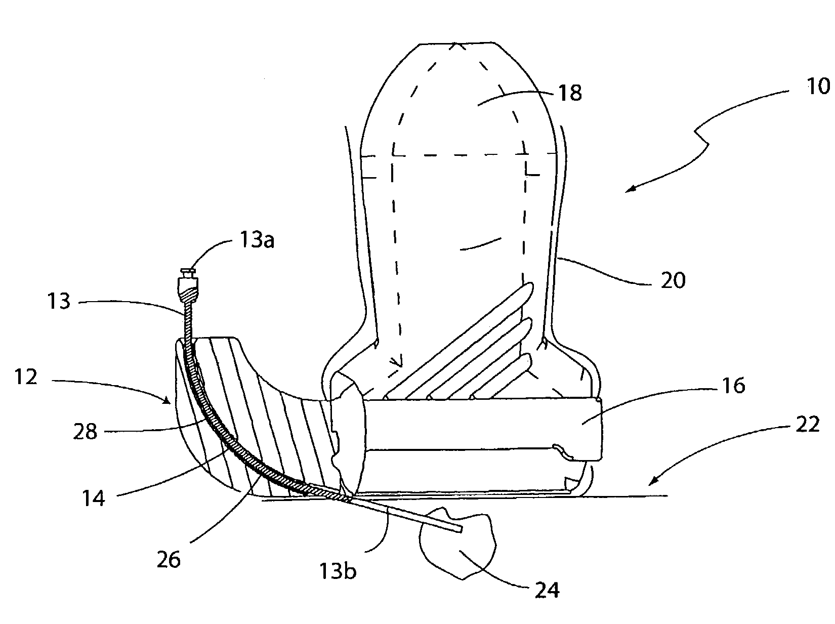
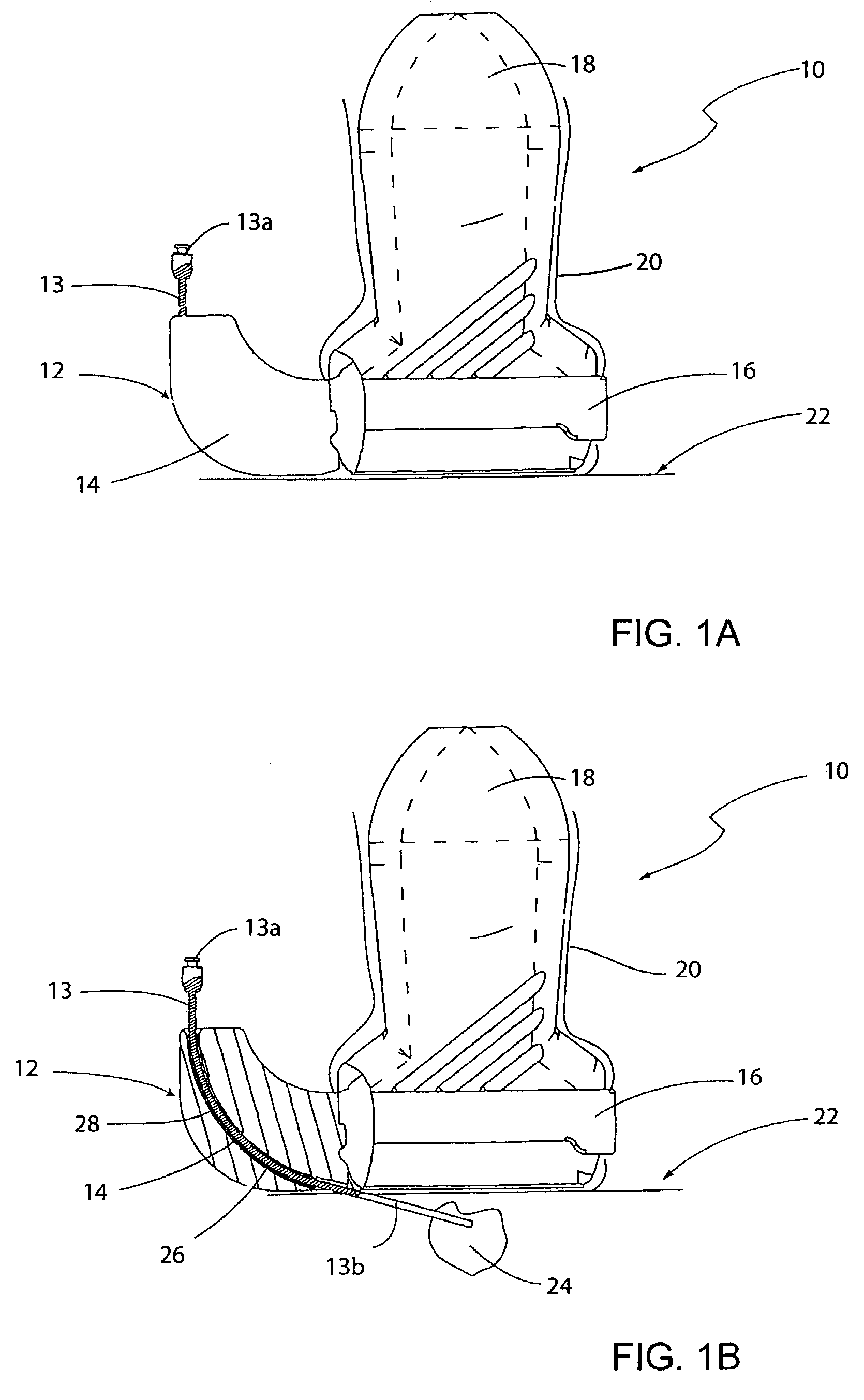
[0032]The present invention is directed to a needle guide for use with an imaging instrument. The needle guide controls the direction of a needle as it enters a patient during imaging analysis, and in particular helps in controlling the angle at which the needle enters a patient. The invention allows a needle to enter a patient at a relatively acute angle, thereby permitting placement of the needle into a relatively shallow target that is near the surface of a patient, such as near the patient's skin or near the exterior of an organ being examined. These organs can include, for example, a breast, thyroid, vein, artery, skin, or other tissue.

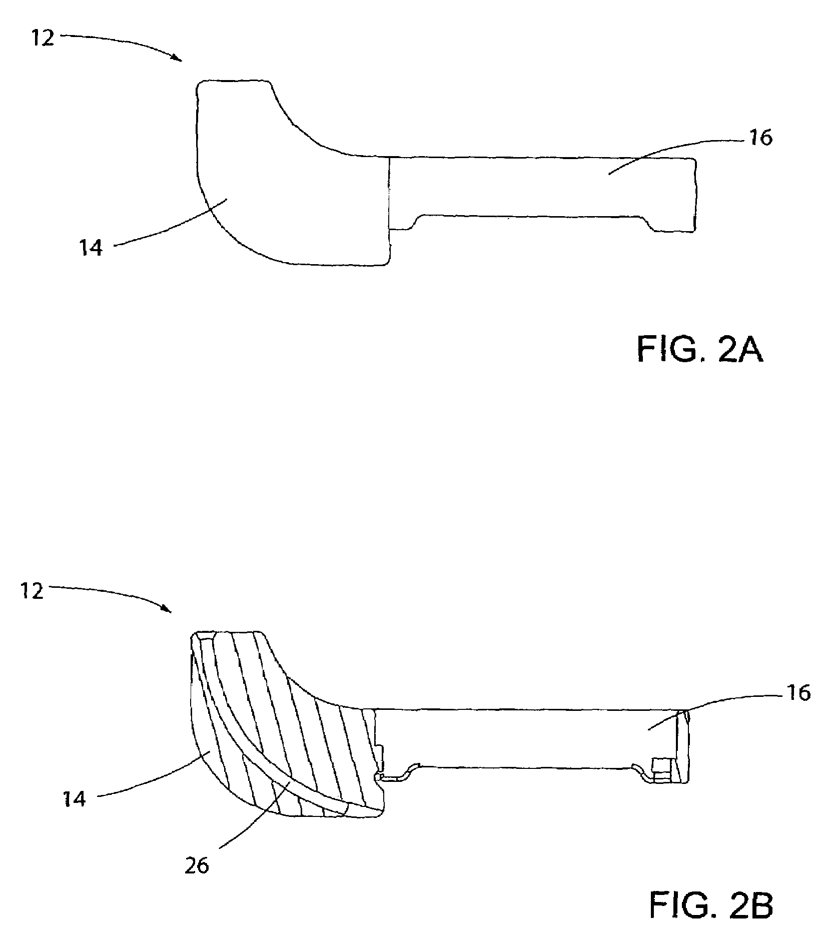
[0033]The needle guide typically includes a curved path that permits a needle to enter the guide at a first angle and then exit the guide at a second angle relative to the surface of a patient. Typically the needle can enter the needle guide at an angle more obtuse to the surface of the patient than when it exits the needle guide. In this manner ...


PUM


Abstract

A needle guide for use with an imaging instrument is disclosed. The needle guide is suitable for delivery of a needle at a shallow angle into a patient during imaging analysis. Thus, the needle guide is well suited to the controlled collection of biopsy tissue or other sample material near the surface of a patient.

Description

FIELD OF THE INVENTION[0001]The present invention relates to a device for guiding a needle into a patient during imaging analysis. More particularly, the invention is directed to an apparatus for guiding a needle into a patient at a shallow angle such that the needle can strike targets near the surface of the patient.BACKGROUND[0002]Imaging instruments, such as ultrasound probes, have revolutionized the manner in which many important medical procedures are performed. These medical instruments utilize substantially non-invasive imaging techniques to explore and assess the condition of human tissue. As a result of these non-invasive imaging techniques, diagnostic and therapeutic protocols have been developed that allow many highly successful and safe procedures to be performed with a minimum of disturbance to patients.[0003]Ultrasound and other imaging techniques have received widespread acceptance as useful diagnostic tools. An ultrasound image, for example, is created by emission of...

Claims


Application Information

Patent Timeline
Patent Type & Authority Patents(United States)
IPC IPC(8): A61B8/00A61B8/08A61B17/34
CPCA61B8/0833A61B8/0841A61B17/3403A61B8/4422A61B2017/3413
Inventor SZCZECH, GERALD S.CERMAK, CRAIGSEVERENCE, BRETT
Owner CIVCO MEDICAL INSTR CO
Why Eureka
Try Eureka