Mobile robotic system and battery charging method therefor

a robotic system and battery charging technology, applied in the field of mobile robotic systems, can solve the problems of automatic battery charging system of robotic vacuum floor cleaners, inability to operate, inconvenience,

Active Publication Date: 2008-04-01
HUNAN GRAND PRO ROBOT TECH
View PDF5 Cites 210 Cited by
  • Summary
  • Abstract
  • Description
  • Claims
  • Application Information

AI Technical Summary

Benefits of technology

[0005]Therefore, the object of the present invention is to provide a battery charging method for a mobile robotic system that can overcome the aforesaid drawbacks associated with the prior art.
[0011]When charging of the rechargeable battery unit is intended, the control unit enables movement of the mobile robot until the first light sensor detects light emitted by the light emitter, subsequently enables rotation of the mobile robot until the second light sensor detects the light emitted by the light emitter, and, while the second light sensor detects the light emitted by the light emitter, enables movement of the mobile robot toward the charging device until the second charging contacts come into contact with the first charging contacts, thereby permitting charging of the rechargeable battery unit via the charging signal.
[0013]When charging of the rechargeable battery unit is intended, the control unit enables movement of the mobile robot until the first light sensor is able to detect light emitted by the light emitter, subsequently enables rotation of the mobile robot until the second light sensor is able to detect the light emitted by the light emitter, and, while the second light sensor detects the light emitted by the light emitter, enables movement of the mobile robot toward the charging device until the second charging contacts are able to come into contact with the first charging contacts, thereby permitting charging of the rechargeable battery unit via the charging signal.

Problems solved by technology

When battery power runs low, the cleaner will not be able to operate.
Hence, inconvenience is encountered since there is a need for the user to check periodically the power level of the rechargeable batteries so that charging of the latter may be conducted under manual supervision whenever the battery power runs low.
Nevertheless, the known automatic battery charging systems for robotic vacuum floor cleaners are disadvantageous in that they involve complex designs that are costly to implement and that require precise alignment between the cleaner and the charging station before battery charging can commence.

Method used


Image

  • Mobile robotic system and battery charging method therefor
  • Mobile robotic system and battery charging method therefor
  • Mobile robotic system and battery charging method therefor

Examples


Embodiment Construction

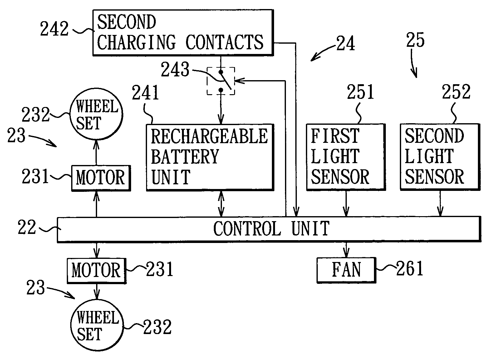
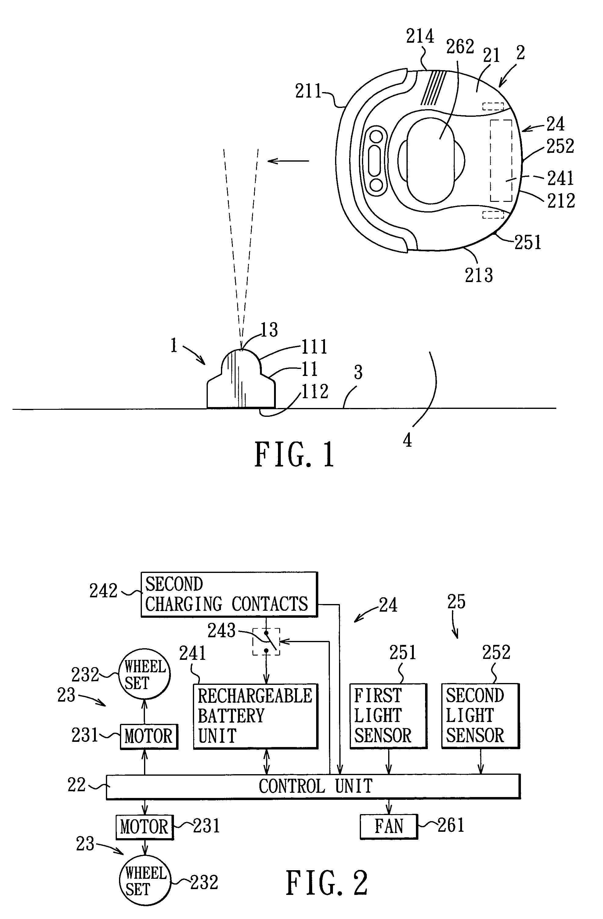
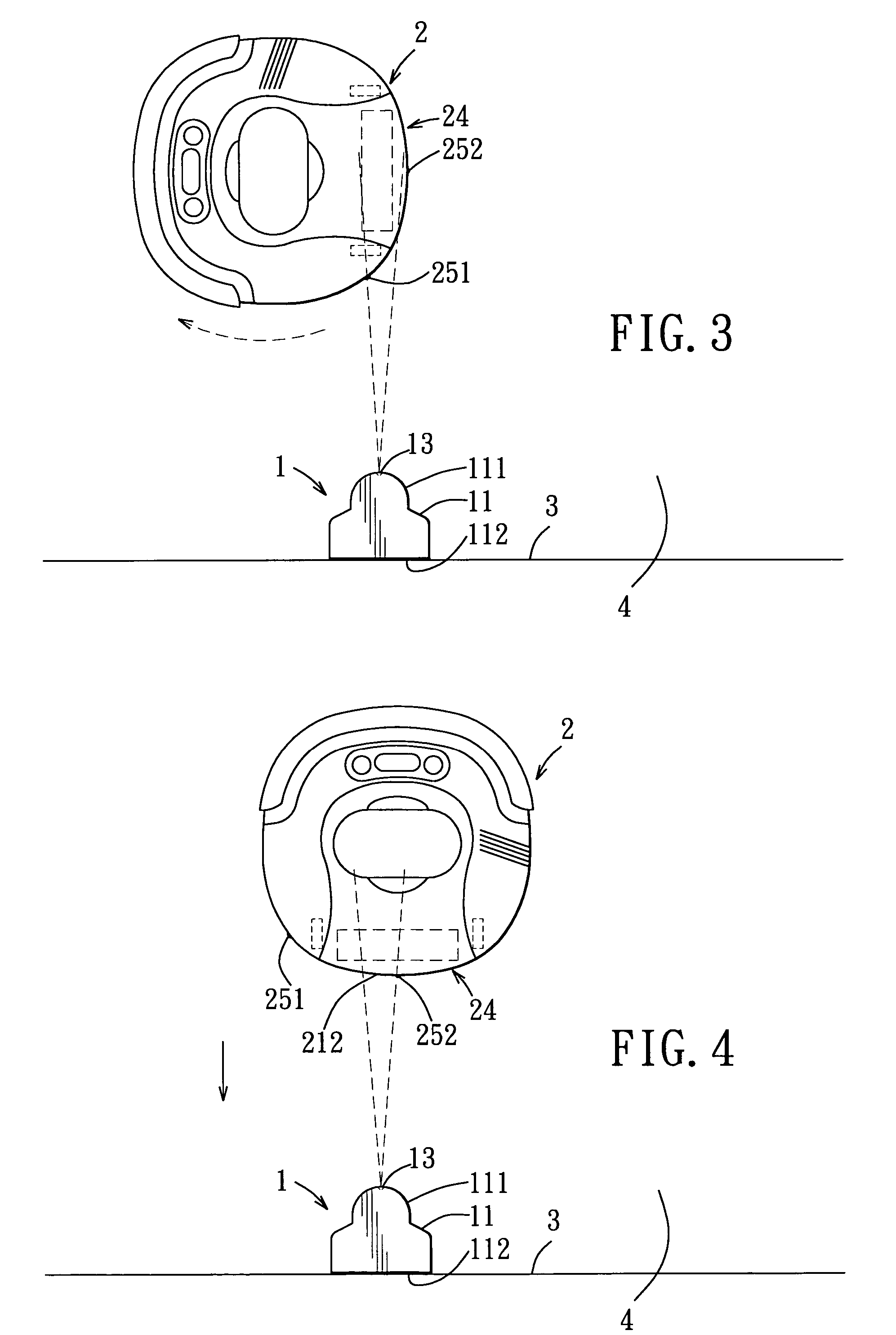
[0024]Referring to FIG. 1, the preferred embodiment of a mobile robotic system according to the present invention is shown to include a charging device 1 and a mobile robot 2. In this embodiment, the mobile robot 2 is exemplified as a robotic vacuum floor cleaner but should not be limited thereto. Moreover, in practice, the mobile robot 2 may be associated with a set of the charging devices 1 that are disposed at different locations so that the mobile robot 2 is able to locate one of the charging devices 1 within a relatively short amount of time so that battery charging can be conducted immediately when battery power runs low.

[0025]Referring to FIGS. 1 and 5, the charging device 1 includes a casing 11, a power cord (not shown) extending from the casing 11 and a transformer (not shown) disposed in the casing 11 and connected to the power cord. The power cord is to be coupled to an electrical socket (not shown) on a wall 3 so that a commercial alternating current (ac) power signal is...


PUM


Abstract

A mobile robotic system includes a charging device and a mobile robot. The charging device is provided with a light emitter and a set of first charging contacts for supplying a charging signal. The mobile robot has a first side provided with a first light sensor, a second side provided with a second light sensor and a set of second charging contacts corresponding to the first charging contacts, a rechargeable battery unit, and a control unit. When charging of the battery unit is intended, the control unit enables movement of the mobile robot until the first light sensor detects light emitted by the light emitter, subsequently enables rotation of the mobile robot until the second light sensor detects the light from the light emitter, and then enables movement of the mobile robot toward the charging device until the first and second charging contacts come into contact.

Description

BACKGROUND OF THE INVENTION[0001]1. Field of the Invention[0002]The invention relates to a mobile robotic system, more particularly to a battery charging method for a mobile robotic system.[0003]2. Description of the Related Art[0004]Robotic vacuum floor cleaners have grown in popularity in recent years due to the rapid reduction in their manufacturing costs. Conventional robotic vacuum floor cleaners generally utilize rechargeable batteries as a source of power. When battery power runs low, the cleaner will not be able to operate. Hence, inconvenience is encountered since there is a need for the user to check periodically the power level of the rechargeable batteries so that charging of the latter may be conducted under manual supervision whenever the battery power runs low. In view of the foregoing, various automatic battery charging systems, such as those disclosed in U.S. Pat. Nos. 4,679,152, 5,682,640 and 5,646,494, for robotic vacuum floor cleaners have been proposed heretofor...

Claims


Application Information

Patent Timeline
Patent Type & Authority Patents(United States)
IPC IPC(8): H02J7/00B25J9/18G05D1/02
CPCG05D1/0225G05D1/0234H02J7/0042A47L2201/022G05D2201/0215G05D1/0242
Inventor YAN, JASON
Owner HUNAN GRAND PRO ROBOT TECH
Why Eureka
Try Eureka