Method and device for detecting gases by absorption spectroscopy

a technology of absorption spectroscopy and gas detection, which is applied in the direction of measurement devices, instruments, scientific instruments, etc., can solve the problems of gas leakage, inability to easily transport instruments requiring such a long tube, and inability to meet the requirements of gas detection, so as to achieve the effect of greatly prolonging the beam length of the test gas

Inactive Publication Date: 2008-04-01
ECOTEC INT HLDG LLC
View PDF6 Cites 63 Cited by
  • Summary
  • Abstract
  • Description
  • Claims
  • Application Information

AI Technical Summary

Benefits of technology

[0028]A method of detecting a preselected gas, such as methane, includes the steps of continuously moving a stream of sample gas through a confined testing area within a detecting instrument. A light source, such as a laser emitting diode or a light emitting diode is energized within the test instrument to emit a beam of frequency that is highly absorbed by the preselected gas. The beam is passed through the stream of gas within the confined testing area by bouncing the beam repeatedly between spaced apart mirrors in a Herriott type cell so that the length of travel of the beam within the test gas is greatly extended. Absorption of the beam is measured to provide an indication of the presence of the preselected gas.
[0034]The invention herein provides a highly portable yet rugged system that it easily adaptable to mounting in a vehicle so that test samples can be continuously picked up from the environment and cycled through the test system while the vehicle is moving to enable an operator to expeditiously survey a relatively large geographical area. This highly portable system used in a vehicle provides readouts coordinated with a global positioning monitor so that gas level intensities of a geographical area can be quickly and accurately mapped.

Problems solved by technology

Since gas is useable only because it is highly combustible, gas leakage is a serious concern.
It is easy to understand that if a beam is passed through a very long tube containing a sample of gas that the instruments requiring such a long tube would be extremely cumbersome and therefore not easily portable.

Method used


Image

  • Method and device for detecting gases by absorption spectroscopy
  • Method and device for detecting gases by absorption spectroscopy
  • Method and device for detecting gases by absorption spectroscopy

Examples


Embodiment Construction

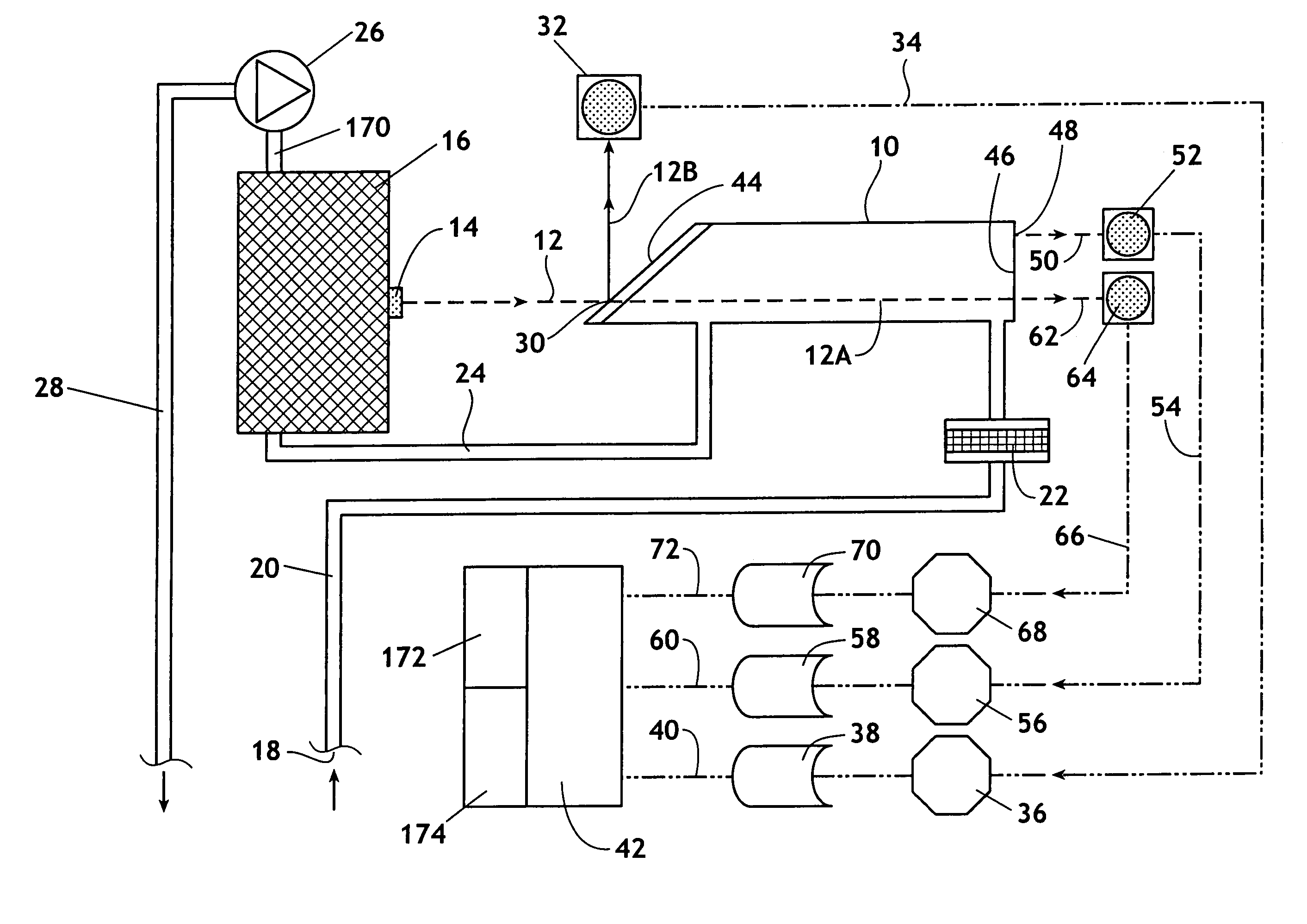
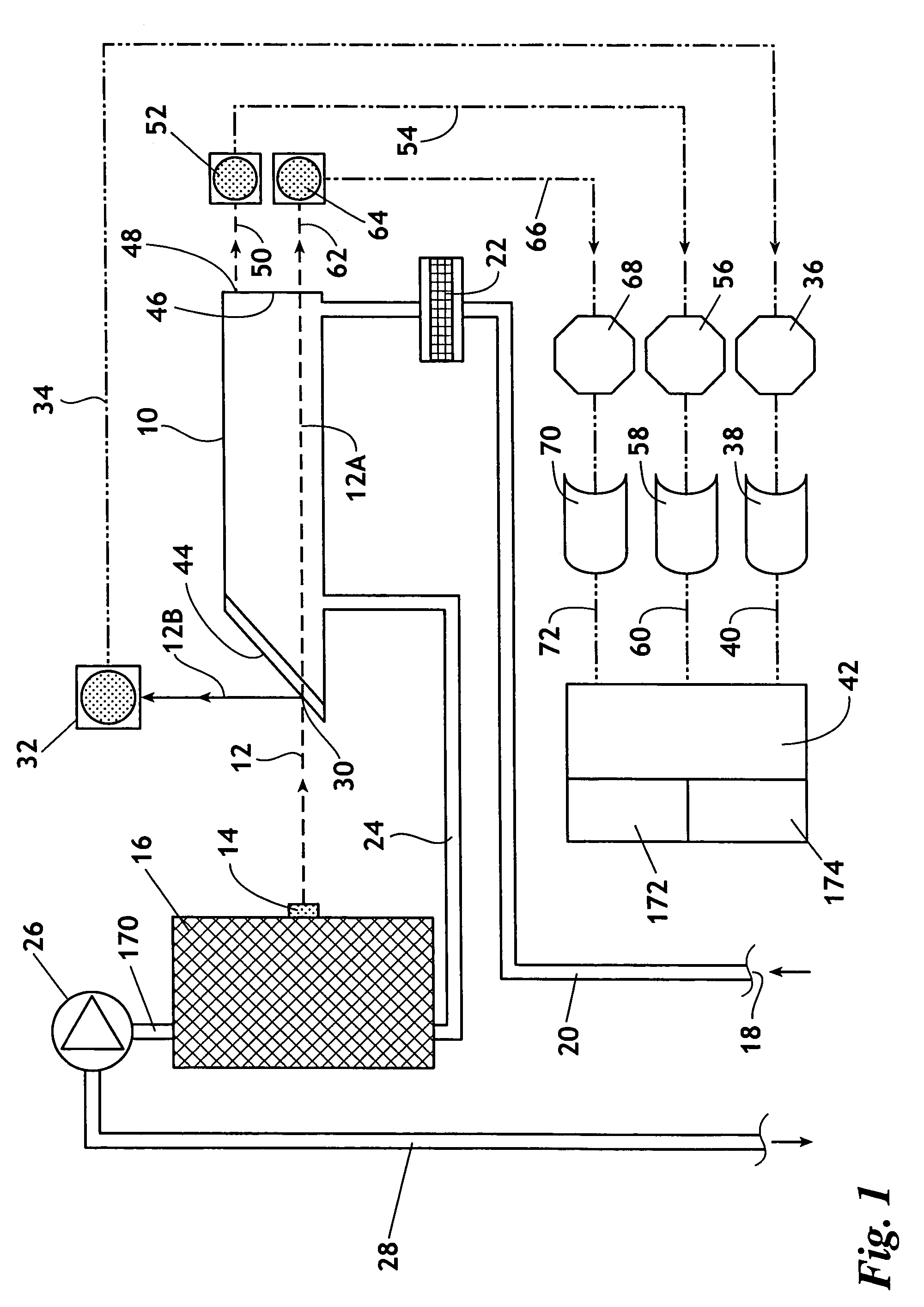
[0047]Referring to the drawings and first FIG. 1, a block diagram of the major components of a system that can be used in practicing the methods of this invention are illustrated. The heart of the system is a cell 10 that will be described in detail subsequently, and that provides an environment in which a light beam 12 passes through a gas sample and in which absorption of the light beam is measured.

[0048]The invention will be described in which a light beam is provided by a laser diode, in which case light beam 12 is a laser light beam. However, the invention can be practiced using a light source that provides a non-coherent light beam. An example of a non-coherent light source is a light emitting diode (LED). A laser diode provides a coherent light beam that is a beam of substantially uniform frequency light having the characteristic that the laser light beam does not disperse to the same extent as a non-coherent light beam. The use of a laser beam, such as produced by a laser di...


PUM

PropertyMeasurementUnit
pressureaaaaaaaaaa
concentrationaaaaaaaaaa
areaaaaaaaaaaa

Abstract

A method and device for measuring a concentration of a preselected gas in a gas sample are disclosed. The device comprises a Herriott type multipass cell (10) having a center axle (74) and a housing (80A, 80B) surrounding and spaced from the axle to provide a tubular sample cavity (84). The gas sample is pumped through the sample cavity via apertures (154, 156) provided in opposed ends of the axle. A first mirror (44) and a second mirror (46) are supported at opposed ends of the axle. A light source, e.g. a laser or LED, is provided for emitting a light beam into the sample cavity via an entry aperture (30) in the first mirror, the light beam having a wave length at which the preselected gas strongly absorbs. The beam is reflected between the mirrors for a number of times before exiting the cell via an exit aperture (48) in the second mirror and impinging on a detector (52). The device further comprises a reference detector (32) for monitoring the intensity of the unattenuated light beam and a detector for detecting the intensity of light transmitted through the second mirror after a single pass through the cell. The light source is operatively connected to a heat control assembly having a heat sink and the gas sample is passed said heat sink to augment temperature control of the light source.

Description

BACKGROUND OF THE INVENTION[0001]A common means of distributing energy around the world is by the transmission of gas, usually natural gas, but in some areas of the world manufactured gasses are also transmitted for use in homes and factories. Gas is typically transmitted through underground pipelines having branches that extend into homes and other buildings for use in providing energy for space and water heating. Many thousands of miles of gas pipeline exists in virtually every major city of the world. Since gas is useable only because it is highly combustible, gas leakage is a serious concern. For this reason much effort has been made to provide instrumentation for detecting small amounts of gas so that leaks can be located to permit repairs.[0002]A known and successful system for detecting small quantities of gas in the environment is by the use of absorption spectroscopy. By this technique, a light beam of a selected frequency that is highly absorbed by the particular gas for w...

Claims


Application Information

Patent Timeline
Patent Type & Authority Patents(United States)
IPC IPC(8): G01N21/00
CPCG01N21/031G01N21/61G01N2201/0668
Inventor BOUNAIX, FABRICE MARCEL S.
Owner ECOTEC INT HLDG LLC
Why Eureka
Try Eureka