Method for computer recognition of projection views and orientation of chest radiographs

a projection view and computer recognition technology, applied in the field of radiograph processing, can solve the problems of introducing errors, insufficient detail of projection profile features, and time-consuming manual generation of template images, so as to avoid interference of collimation areas and other noise, promote efficiency, and promote robustness.

Inactive Publication Date: 2008-04-01
CARESTREAM HEALTH INC
View PDF10 Cites 10 Cited by
  • Summary
  • Abstract
  • Description
  • Claims
  • Application Information

AI Technical Summary

Benefits of technology

[0021]The present invention provides some advantages. Features of the system and method promote robustness. For example, preprocessing of chest radiographs helps to avoid the interference of collimation areas and other noise. In addition, features used for classification are invariant to size and translation. Hence, it can handle a fair degree of orientation variance. Yet further, the system is not dependent on capture device characteristics, so accordingly, the system / method can be employed for digitized films as well as for digital x-ray images, for example, those obtained by means of CR and DR (digital radiography) techniques. Features of the system and method also promote efficiency. For example, the computation complexity is under O(n), where n is the total number of pixels in an image, which can be reduced if the classification is implemented on a sub-sampled coarse resolution image.

Problems solved by technology

However, the two profiles mentioned in the above methods are very sensitive to noise in the images and the projection profile's features are not sufficiently detailed to allow differentiation of the PA and LAT projection views.
However, the manual generation of the template images is quite time consuming, and more particularly, is highly observer dependent, which can introduce error into the classification.
However, both template-matching methods suffer problems in handling rotation and translation variance of an individual patient's chest radiograph.
In addition, the methods do not address the interference of noise or unrelated regions which can cause seriously biased classification results.
The method is disadvantaged for actual application since it is quite complicated; the rules are based only on the boundary information of the images, which is not reliable in most chest images because of variability of patient's position in the images and the existence of collimation areas in some images; and no actual image content information, such as lung regions, is considered in the method.

Method used


Image

  • Method for computer recognition of projection views and orientation of chest radiographs
  • Method for computer recognition of projection views and orientation of chest radiographs
  • Method for computer recognition of projection views and orientation of chest radiographs

Examples


Embodiment Construction

[0034]The following is a detailed description of the preferred embodiments of the invention, reference being made to the drawings in which the same reference numerals identify the same elements of structure in each of the several figures.

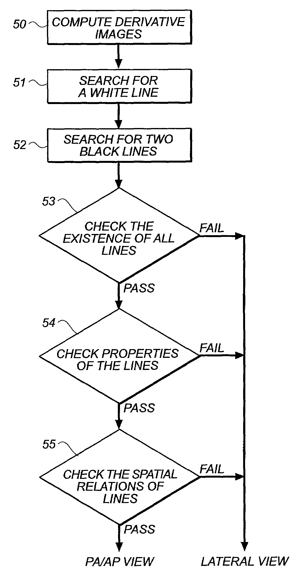
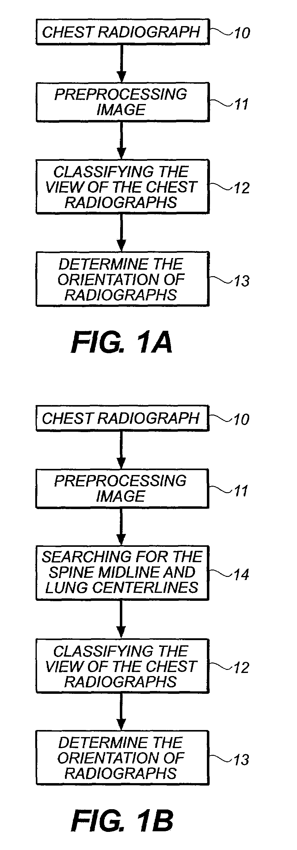
[0035]The present invention is directed to a system and method for automatically identifying the projection view and orientation of chest radiographic images. A flow chart of a method in accordance with the present invention is generally shown in FIG. 1A. As shown in FIG. 1A, the method includes three processing steps. First, the input chest radiograph image (step 10) is pre-processed (step 11). Then, three feature lines are detected and a set of features is extracted and compared with the general characteristics of chest PA / AP views to classify chest radiographs (step 12). Finally the orientation of the radiograph is determined (step 13).

[0036]In a further embodiment, shown in the flow chart of FIG. 1B, an additional step can be applied prior to th...


PUM


Abstract

A method for identifying a projection view and an orientation of a chest radiograph. The method includes the steps of: providing an input digital image of the chest radiograph; preprocessing the input digital radiographic image; classifying the view of the input digital radiographic image; and determining the orientation of the input digital radiographic image.

Description

FIELD OF INVENTION[0001]The present invention relates generally to techniques for the processing radiographs, and more particularly to techniques for automated processing of chest radiographs. More specifically, the present invention is directed to techniques for automatically recognizing the projection views and orientation of chest radiographs.BACKGROUND OF THE INVENTION[0002]Chest radiography is a widely used technique in diagnostic imaging of medical images. It can make up at least a third of all conventional diagnostic radiographic procedures in a general hospital. A conventional radiographic chest examination includes two projection views. One view is a posterior-anterior (PA) or anterior-posterior (AP) projection view, while the other view is a lateral (LAT) projection view.[0003]Medical professionals using such radiographic chest examinations often prefer to view the images in standardized ways, which require the proper position of the image with a particular view (i.e., AP / ...

Claims


Application Information

Patent Timeline
Patent Type & Authority Patents(United States)
IPC IPC(8): G06K9/00
CPCG06T7/0042G06T2207/30061G06T7/73
Inventor LUO, HUICORNELIUS, CRAIG W.
Owner CARESTREAM HEALTH INC
Why Eureka
Try Eureka