Positive locking push-on precision 3.5 mm or 2.4 mm connector for an oscilloscope probe

a technology of push-on and connector, which is applied in the direction of coupling device connection, engagement/disengagement of coupling parts, instruments, etc., can solve the problems of affecting the fidelity of transmitted signals, affecting the physical size of coaxial transmission lines, and more conveniently manipulated connectors (e.g., bnc) being unsuitable for high frequency servi

Inactive Publication Date: 2008-04-08
AGILENT TECH INC
View PDF18 Cites 14 Cited by
  • Summary
  • Abstract
  • Description
  • Claims
  • Application Information

AI Technical Summary

Benefits of technology

[0008]A positive locking push-on 3.5 mm (or 2.4 mm) connector is provided by retaining the bayonet latch of the BNC-style push-on latch mechanism and associated male and female outer conductor shells, but which is sized for 3.5 mm (or 2.4 mm) use, while providing (for 3.5 mm) SMA / APC-3.5 style male and female center conductor pins that are held in place within their respective outer conductor shells by RF beads that are part of a unitized transmission line subassembly. Alteration of certain axial dimensions of the outer conductor shells prevents the accidental mating of the 3.55 mm (2.4 mm) bayonet connector with a BNC connector of the opposite gender, and does so in a way that prevents damage to any of the center pins.

Problems solved by technology

As is well known, the characteristic impedance of a transmission line is affected by its mechanical dimensions, and the presence of a connector between two sections of a coaxial transmission line is an opportunity for unwanted changes in Z0 (discontinuities) that cause reflections and impair the fidelity of the transmitted signal.
Not all high frequency connectors are created equal, and it is often the case that the more conveniently manipulated connectors (e.g., BNC) are ill suited for high frequency service (standard BNC begins to ‘leak’ above 500 MHz, and is extremely visible as a significant discontinuity on a TDR—a Time Domain Reflectometer).
As service at ever higher frequencies is contemplated the physical size of the coaxial transmission line becomes an issue.
Smaller cables mean smaller connectors, which in turn are more delicate and more easily damaged than their larger counterparts.
Another issue concerning high frequency oscilloscope probes is that they are generally active probes, meaning that there is an actual powered amplifier at their ‘business end’ near where the probe tip is, and that not only must the front panel connection at the 'scope accommodate a 3.5 mm connector for a transmission line, but also various conductors for power, ground, and ‘house-keeping’ information must be dealt with.

Method used


Image

  • Positive locking push-on precision 3.5 mm or 2.4 mm connector for an oscilloscope probe
  • Positive locking push-on precision 3.5 mm or 2.4 mm connector for an oscilloscope probe
  • Positive locking push-on precision 3.5 mm or 2.4 mm connector for an oscilloscope probe

Examples


Embodiment Construction

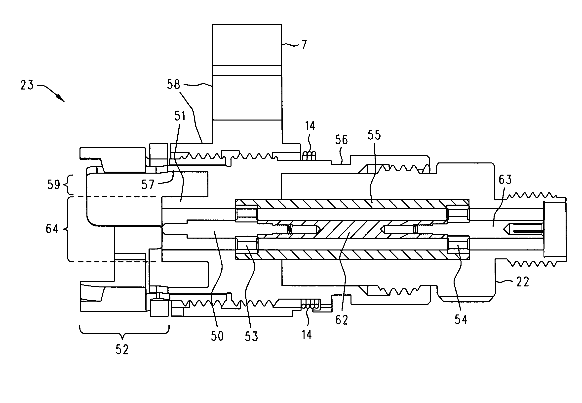
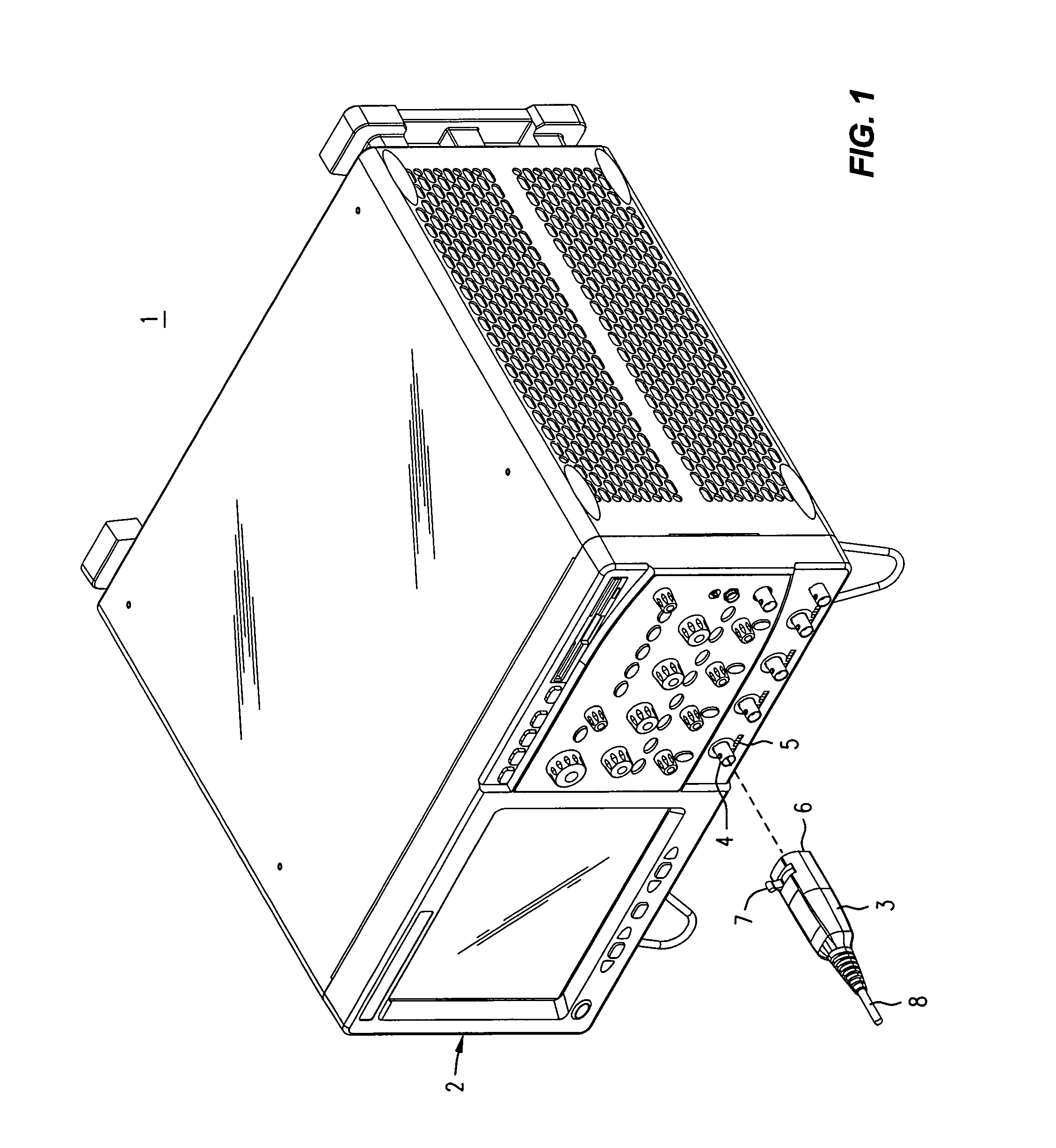
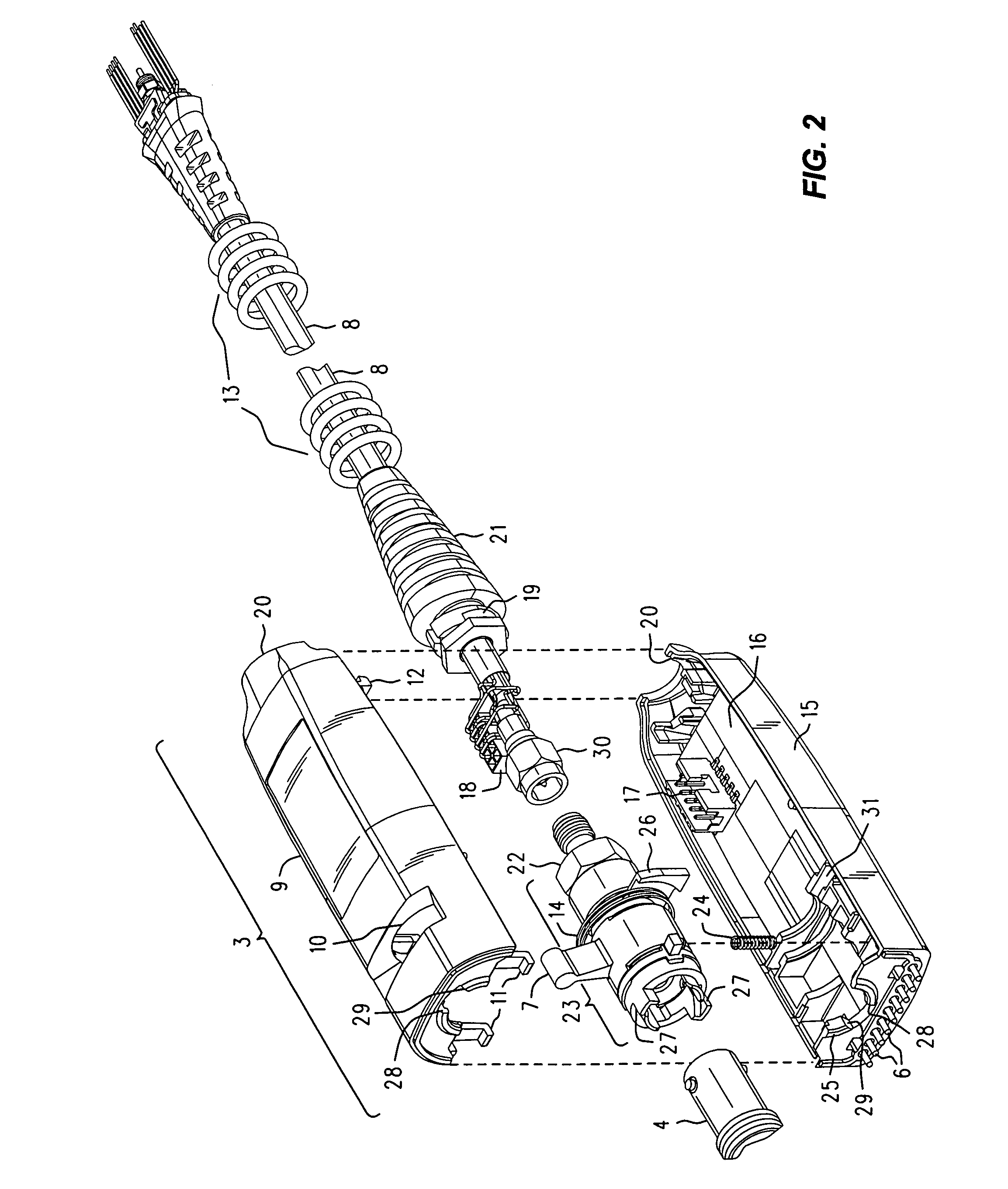
[0013]Refer now to FIG. 1, wherein is shown a front perspective view 1 of an electronic instrument 2, such as a digital oscilloscope, having one or more front panel precision female 3.5 mm bayonet latch connectors 4 that receive a positive locking push-on precision male 3.5 mm bayonet latch connector assembly 3 (probe pod housing), say, in support of operation with an active probe (not shown) connected at a distal end of a cable 8. It will be appreciated that, although our explanation will proceed for the 3.5 mm connector, what is said and shown applies equally well to the case of a 2.4 mm connector.

[0014]In a manner similar to that explained in another U.S. Pat. No. (6,095,841) that is itself incorporated in the '099 Patent incorporated herein, the positive locking push-on precision male 3.5 mm bayonet latch connector probe pod housing is installed by first lining it up and then pushing it toward the 'scope. That engages the 3.5 mm bayonet latch detents, and a simple motion with th...


PUM


Abstract

A positive locking push-on 3.5 mm (or other diameter, such as 2.4 mm) connector is provided by retaining an existing bayonet lug and latch style push-on latch mechanism and associated male and female outer conductor shells, but which is sized for 3.5 mm use, while providing SMA / APC-3.5 style male and female center conductor pins that are held in place within their respective outer conductor shells by RF beads that are part of a unitized transmission line subassembly. Alteration of certain axial dimensions of the outer conductor shells prevents the accidental mating of the 3.5 mm bayonet connector with a BNC connector of the opposite gender, and does so in a way that prevents damage to any of the center pins.

Description

REFERENCE TO RELATED APPLICATION[0001]The subject matter of this Application is related to that of U.S. Pat. No. 6,884,099 B1. For brevity and the sake of completeness, U.S. Pat. No. 6,884,099 B1 (the '099 Patent) is hereby expressly incorporated herein by reference. A perusal of the '099 Patent would reveal that it incorporates U.S. Pat. No. 6,095,841.INTRODUCTION AND BACKGROUND[0002]The connectors that attach cables to high frequency test equipment, such as oscilloscopes, have a significant effect on the fidelity, and even the very ability, of the connection to convey the signal of interest. This arises from the customary practice of using an actual transmission line with a controlled characteristic impedance (Z0), which is often 50 Ω, as the connecting medium between the test equipment and the work piece. As is well known, the characteristic impedance of a transmission line is affected by its mechanical dimensions, and the presence of a connector between two sections of a coaxial...

Claims


Application Information

Patent Timeline
Patent Type & Authority Patents(United States)
IPC IPC(8): H01R13/62
CPCG01R1/06788G01R1/06772H01R13/625
Inventor CANNON, JAMES E.
Owner AGILENT TECH INC
Why Eureka
Try Eureka