Electrical tool

a technology of electric tools and permanent magnet motors, applied in the field of electric tools, can solve problems such as the degradation of mounting performance, and achieve the effects of smooth insertion into the housing, excellent workability, and smooth assembly of permanent magnet motors

Inactive Publication Date: 2008-04-08
KOKI HLDG CO LTD
View PDF5 Cites 19 Cited by
  • Summary
  • Abstract
  • Description
  • Claims
  • Application Information

AI Technical Summary

Benefits of technology

[0010]An object of the present invention is to provide an electrical tool in which a permanent magnet motor can be smoothly mounted without requiring excess working power and man-hour.
[0016]According to the first and second aspects, when the rotor is inserted into the housing such that the permanent magnet motor is mounted, the protrusions of the plate first come in contact with the inner circumferential surface of the stator to prevent the rotor core from being attracted to the magnet although the rotor core is attracted to the stator by magnetic flux of the magnet. Thus, the rotor is always separated from the stator and the rotor can be smoothly inserted into the housing while being guided by the plate. In addition, it is possible to smoothly assemble the permanent magnet motor with excellent workability, without requiring excess working power or man-hour.
[0017]In addition, since the shaft and the stator are coaxially held by the plate, axial misalignment between the shaft and the housing bearing portion is removed, and the plate functions as a guide for accurately guiding the bearing attached to the end of the shaft into the housing bearing portion. Since the bearing is always accurately fitted into the housing bearing portion, assembling performance of the permanent magnet motor is improved.
[0018]According to the third aspect, since the protrusions of the plate are disposed outer than the axial ends of the stator in the axial direction, the plate which rotates while the permanent magnet motor is driven does not come in contact with the permanent magnet and the rotor can smoothly rotate.
[0019]According to the fourth aspect, since at least one of the protrusions of the plate is positioned in the inner surface of the magnets of the stator, the rotor is always separated from the stator by action of the protrusions of the plate. In addition, the permanent magnet motor can be smoothly mounted without requiring excess working power or man-hour.
[0020]According to the fifth aspect, since the protrusions of the plate function as a guide for holding coaxially the shaft and the rotor with respect to the stator such that axial misalignment between the bearing and the housing bearing portion is prevented from being generated until the bearing attached to the end of the shaft is inserted into the housing bearing portion, it is possible to mount the permanent magnet motor with more excellent workability.

Problems solved by technology

Accordingly, mounting performance deteriorates.

Method used


Image

  • Electrical tool
  • Electrical tool
  • Electrical tool

Examples


first embodiment

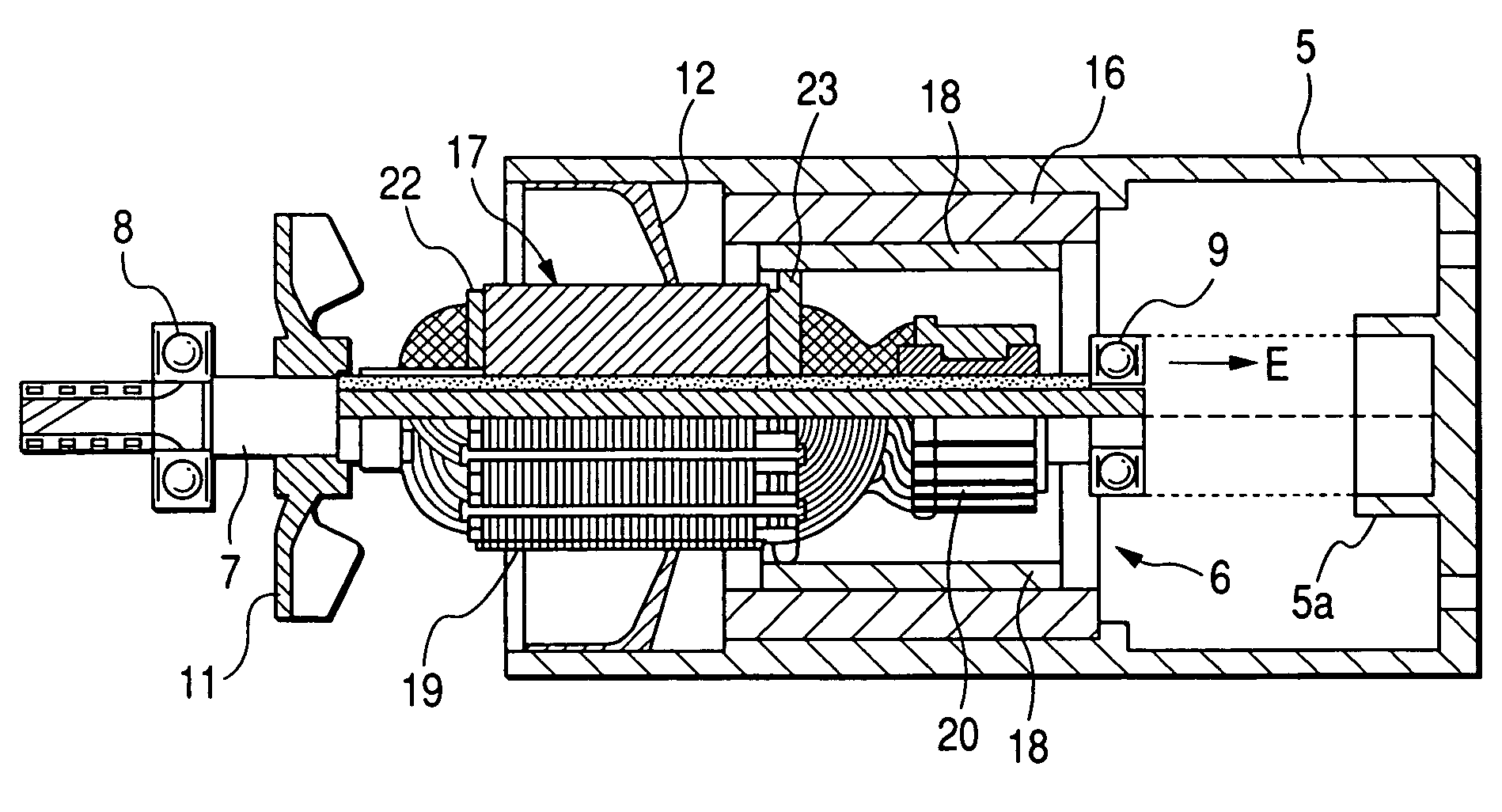
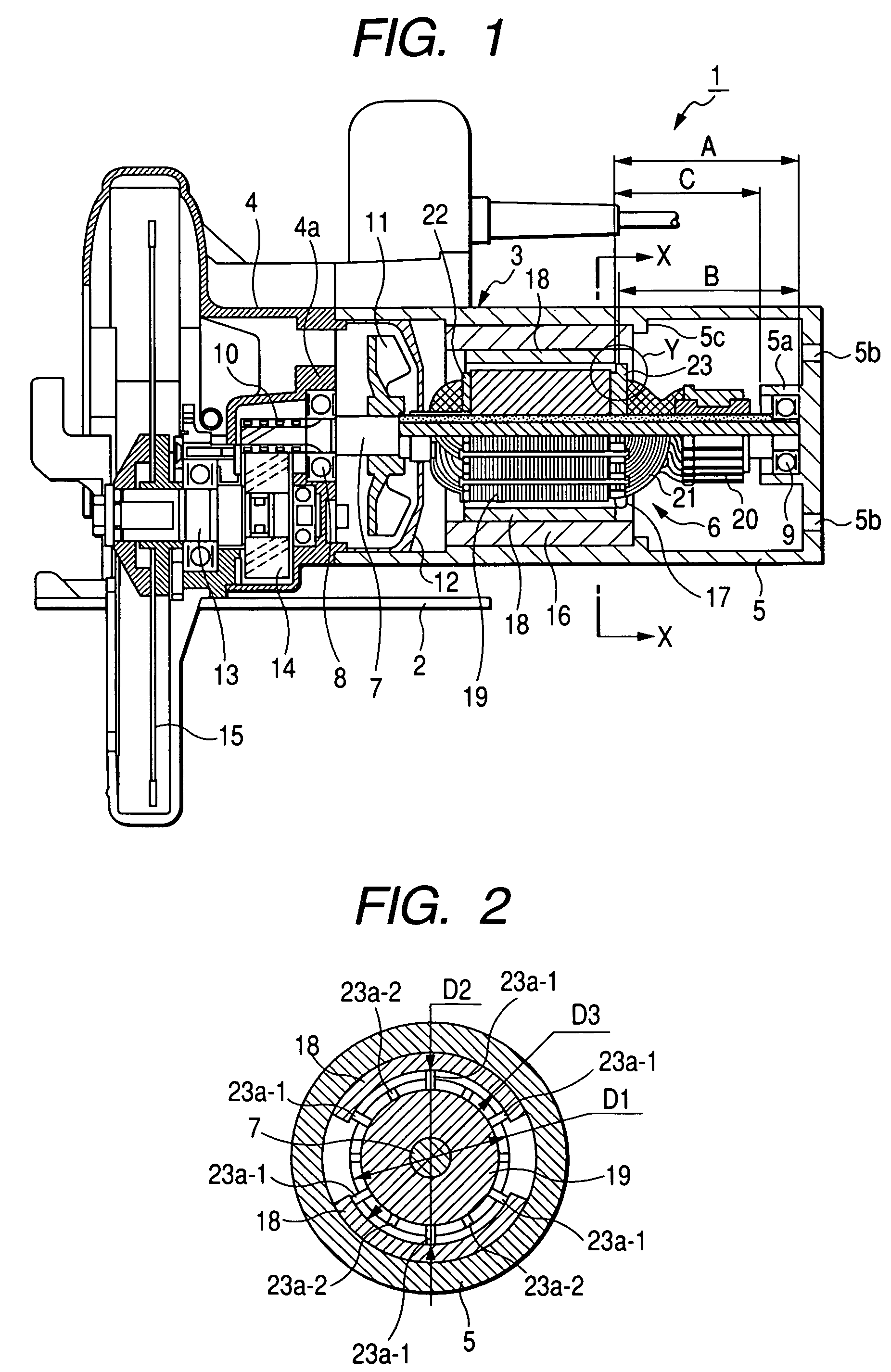
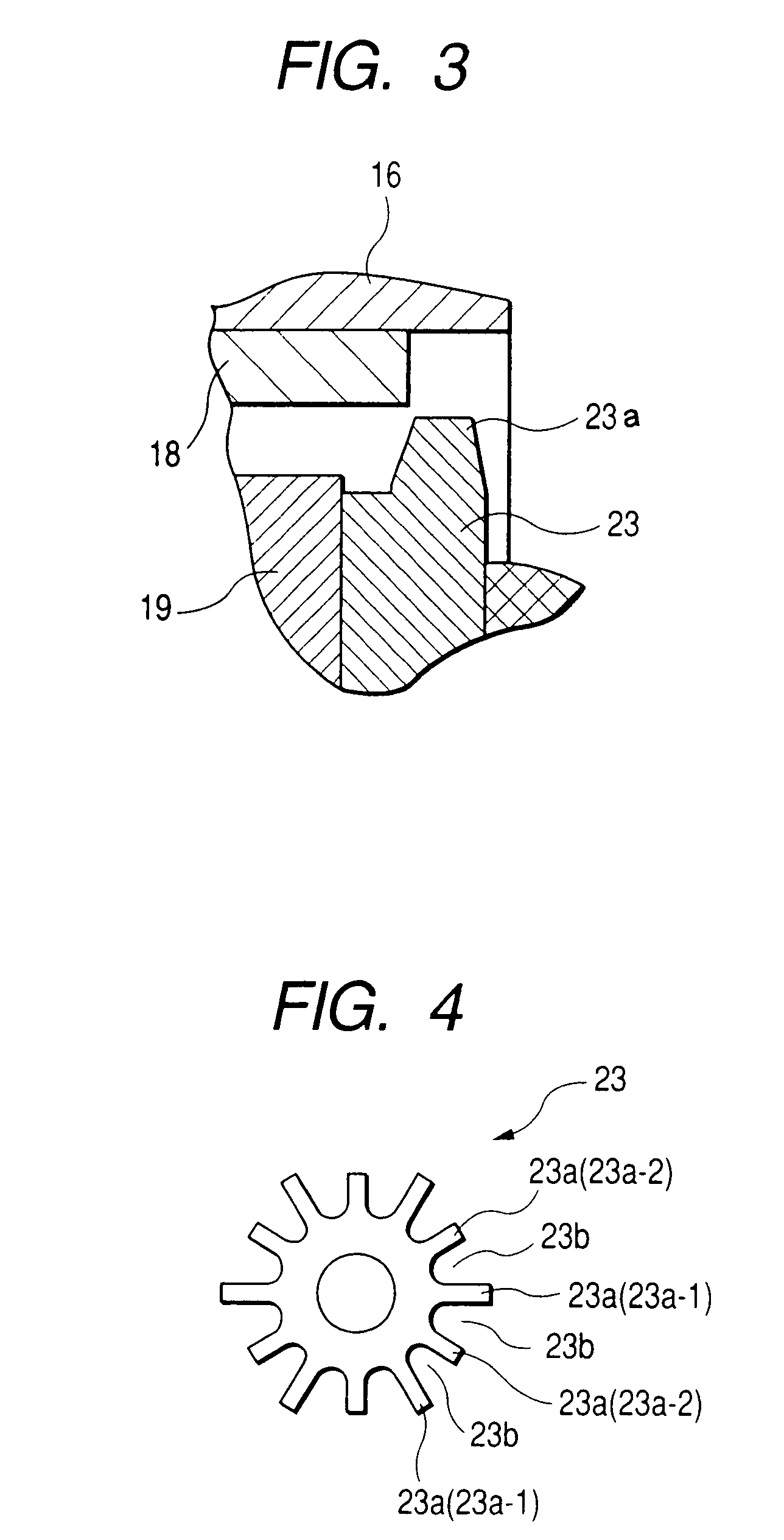
[0029]FIG. 1 is a side cross-sectional view of a portable electrical circular saw according to a first embodiment of the present invention, FIG. 2 is a cross-sectional view taken along line X-X of FIG. 1, FIG. 3 is an enlarged detailed view of a Y portion of FIG. 1, FIG. 4 is a front view of a plate, and FIG. 5 is a partial side cross-sectional view showing a method of mounting a commutator motor.

[0030]In the portable electrical circular saw 1 shown in FIG. 1, reference numeral 2 denotes a base and reference numeral 3 is a housing. The housing 3 is configured by integrally bonding an inner case 4 of a front portion and a motor case 5 of a rear portion. In addition, a commutator motor 6 is mounted in the motor case 5. A front end of a shaft 7 which is an output shaft of the commutator motor 6 is rotatably supported by a bearing portion 4a through a bearing 8 and a rear end thereof is rotatably supported by a bearing portion (hereinafter, referred to as “housing bearing portion) 5a of...

second embodiment

[0054]Next, a second embodiment of the present invention will be described with reference to FIG. 6.

[0055]FIG. 6 is a side cross-sectional view of a commutatorless motor portion of an electrical tool according to the second embodiment of the present invention. In the figure, the same elements as those shown in FIG. 1 are denoted by the same reference numerals and their description will be omitted.

[0056]A commutatorless motor 6′ used as a driving source of the electrical tool according to the present embodiment is characterized in that the permanent magnet 18 is provided on the rotator core 19 and the stator 16 in the vicinity thereof is composed of a winding coil. In the commutatorless motor 6′ having this configuration, the same plate 23 as that of the first embodiment is disposed on the rear end (which is first inserted into the motor case 5 when mounting the commutatorless motor 6′) of the rotator core 19.

[0057]Accordingly, in the present embodiment, the same effect as that of th...


PUM

PropertyMeasurementUnit
outer diameteraaaaaaaaaa
inner diameteraaaaaaaaaa
distanceaaaaaaaaaa

Abstract

In the portable electrical circular saw (electrical tool) in which a commutator motor (permanent magnet motor) is mounted in a motor case (housing) which is integrally formed in a tube shape, the commutator motor includes a stator fixed to an inner circumferential surface of the motor case and a rotor which is rotatably disposed in the stator, and a plate having a plurality of protrusions is disposed on at least one of the both axial ends of a rotor core of the rotor, an outer diameter of at least two protrusions of the plate is larger than an outer diameter of the rotor core and smaller than an inner diameter of the stator.

Description

BACKGROUND OF THE INVENTION[0001]1. Field of the Invention[0002]The present invention relates to an electrical tool including a permanent magnet motor as a driving source.[0003]2. Description of Related Art[0004]A permanent magnet motor such as a commutator motor capable of obtaining a high output with a small size is used as a driving source of an electrical tool (for example, see Patent Document 1). In an electrical tool using a commutator motor as a driving source, as shown in FIG. 7, a commutator motor 106 includes a stator 116 fixed to an inner circumferential surface of a motor case 105 and a rotor 117 rotatably disposed in the stator 116. In addition, plates 122 and 123 including a plurality of slot portions having the substantially same shape as that of slots of a rotor core 119 and protrusions are disposed at the both axial ends of the rotor core 119 of the rotor 117.[0005]As shown in FIG. 7, in the electrical tool including the motor case 105 which is integrally formed in ...

Claims


Application Information

Patent Timeline
Patent Type & Authority Patents(United States)
IPC IPC(8): H02K1/22
CPCB23D45/16B23D47/12H02K15/16H02K7/145Y10T29/49009H02K23/04
Inventor YOKOTA, TOMOYOSHIYOSHIDA, HIROKAZUGUNJI, SATORU
Owner KOKI HLDG CO LTD
Why Eureka
Try Eureka