Image scanning apparatus, method and business machine using the same

a scanning apparatus and image technology, applied in the direction of electrographic process, printing, instruments, etc., can solve the problems of affecting the quality of the document, the tendency of the document to bend, and the insufficient pressure on the thick original to press against the platen,

Active Publication Date: 2008-04-08
SEIKO EPSON CORP
View PDF6 Cites 28 Cited by
  • Summary
  • Abstract
  • Description
  • Claims
  • Application Information

AI Technical Summary

Benefits of technology

[0016]The scanner of this invention can press both thick originals and thin originals of greatly different thickness against th

Problems solved by technology

Additional means for holding the pressure setting is therefore unnecessary.
As a result, when particularly thick documents, which exceed this thickness range need to be scanned such as a driver's license and card stock (referred to below as “thick originals”), the pressure on the thick original may be insufficient to press it against the platen and have little resistance to the tendency of the document to bend.
On the other hand, if the pressure is set for thick originals and a document which is thinner than the set thickness range (a “thin original”) is then scanned, the excessive pressure could wrinkle the original and cause document feed errors, e.g. paper jams.
Furthermore, the surface of the origin

Method used


Image

  • Image scanning apparatus, method and business machine using the same
  • Image scanning apparatus, method and business machine using the same
  • Image scanning apparatus, method and business machine using the same

Examples


first embodiment

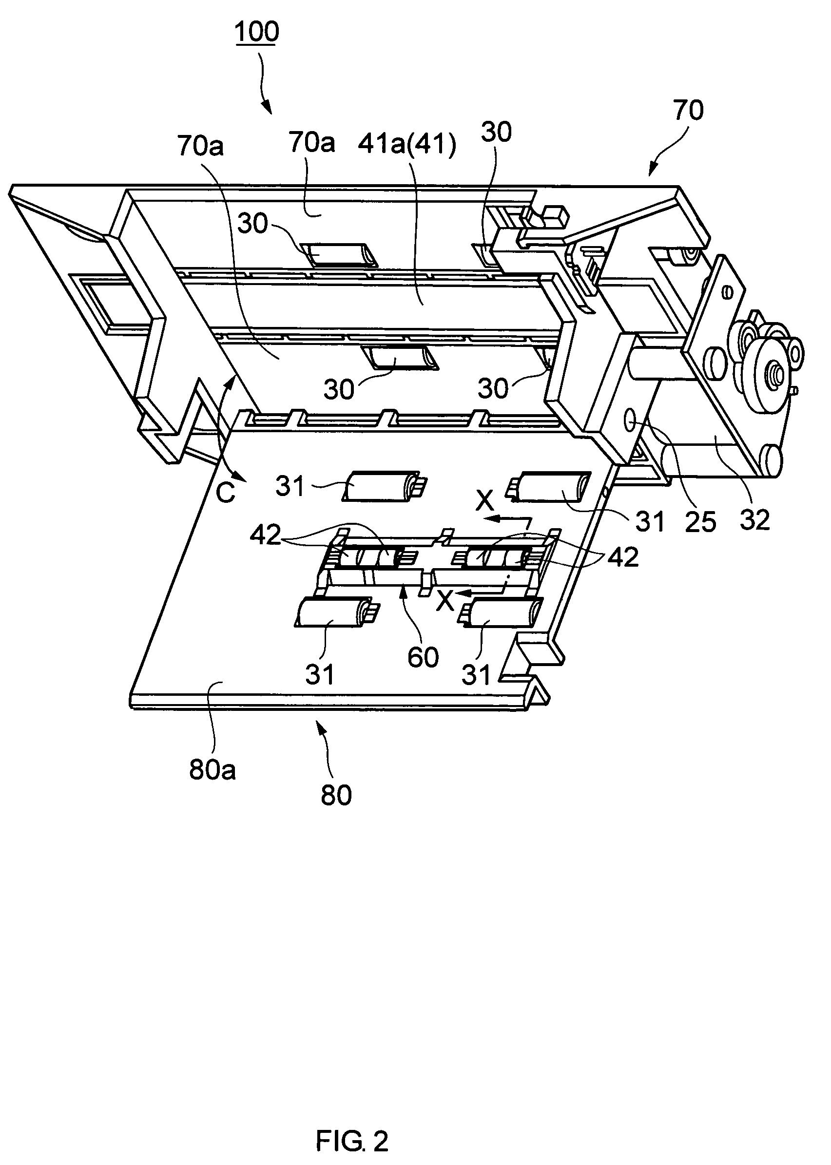
[0055]FIG. 2 to FIG. 5 illustrate a more specific application of the above-described pressure-generating mechanism 50. FIG. 2 is a perspective view of the first embodiment of a scanner and FIG. 3 is a partial perspective view of the main parts of this scanner. FIG. 4 and FIG. 5 are sectional views of the scanner through line X-X in FIG. 2. FIG. 4 is a sectional view when a thin original is inserted, and FIG. 5 is a sectional view when scanning a thick original.

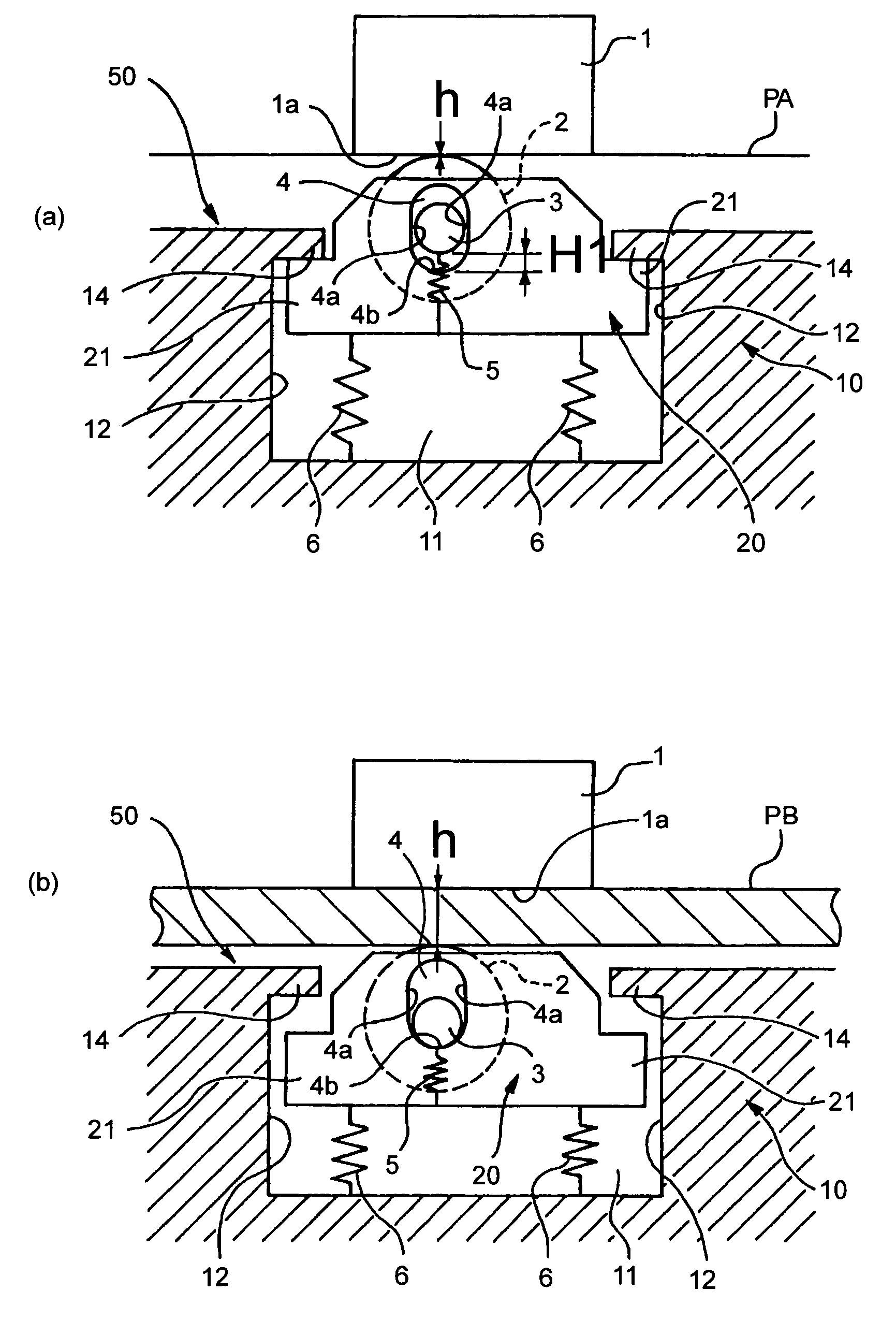
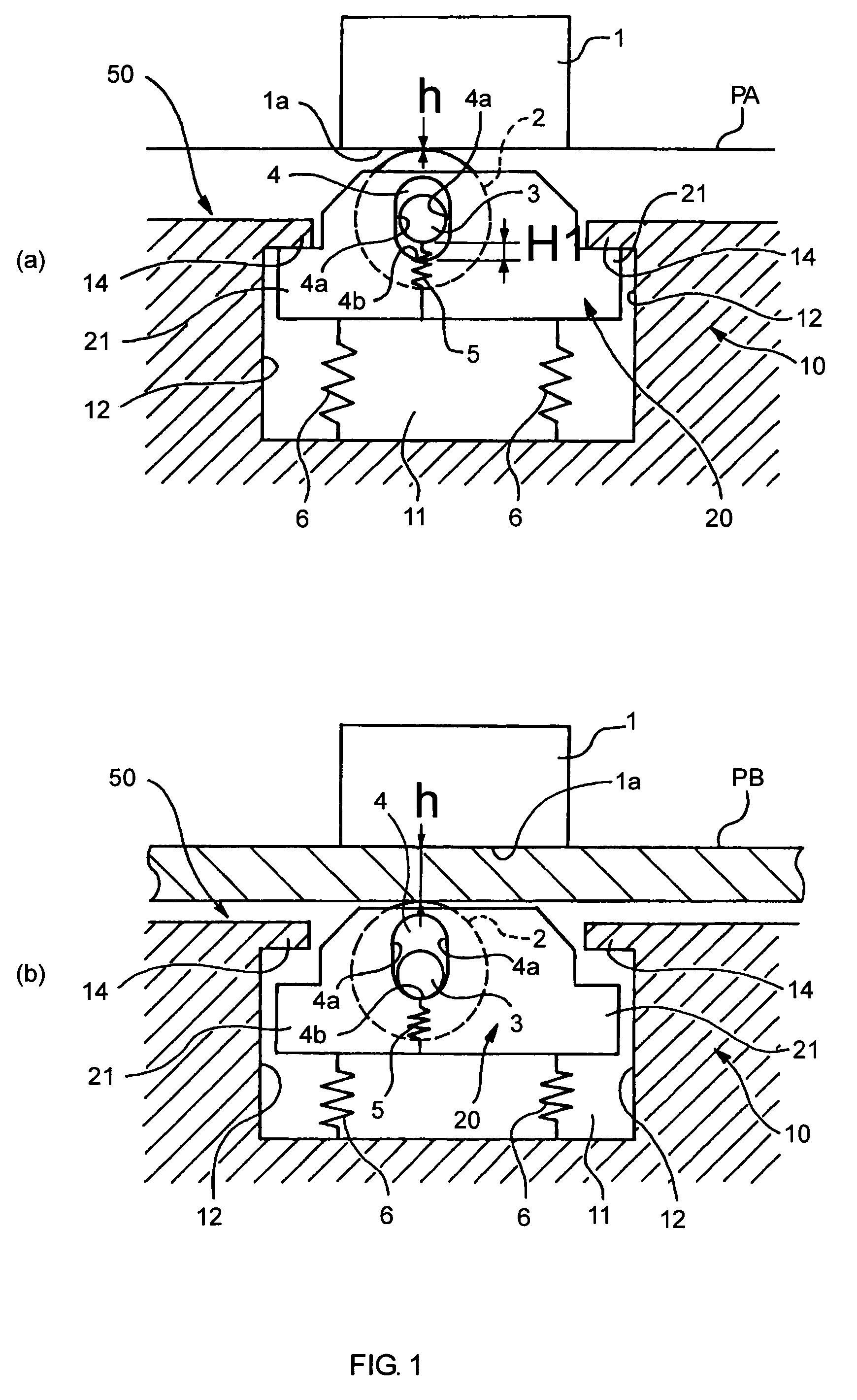
[0056]The scanner 100 shown in FIG. 2 is mounted to a main frame 70 comprising a drive system by means of a hinge 25 enabling a paper guide cover 80 (corresponding to the fixed guide 10 in FIG. 1) to freely open and close in the direction indicated by arrow C in FIG. 2.

[0057]Mounted to the main frame 70 is a motor 32, four paper feed drive rollers 30 that are linked to and driven by the motor 32, and a contact image sensor 41.

[0058]The contact image sensor 41 is disposed between the drive rollers 30. As shown in FIG. 4, the sc...

second embodiment

[0098]Another embodiment of a scanner according to the present invention is described hereafter with reference to FIG. 7 to FIG. 14.

[0099]FIG. 7 is a perspective view showing a business machine 200 equipped with a scanner 110 of FIG. 8 according to a second embodiment of the present invention.

[0100]This business machine 200 is a multiple function printer equipped with a scanner, and can print on both roll paper, not shown, and slip paper, not shown, and can, furthermore, scan and capture information from both slip forms and cards.

[0101]This business machine 200 has an integrally formed bottom housing part 211, a front housing part 212, and a top cover unit 213. The bottom housing part 211 holds a roll of paper, not shown, and has a printing mechanism for printing on roll paper drawn off this roll. The front housing part 212 is disposed at the front of bottom housing part 211 and has a slip paper feed path 221 for transporting slips between the front housing part 212 and bottom housi...


PUM


Abstract

Scanning errors and document feed errors are prevented by pressing originals, including thin originals and thick originals of greatly different thicknesses, to the scanning surface (1a) of an image sensor (1) with pressure appropriate for the respective original. A pressure-generating mechanism (50) is used to press the original against the scanning surface (1a) by selecting different elastic bodies with different spring forces to produce a different elastic force in accordance with the thickness of the original document.

Description

FIELD OF INVENTION[0001]The present invention relates to an image scanning apparatus and method using a contact image sensor for reading image information from a document and to a business machine using the image scanning apparatus.BACKGROUND[0002]Image scanning apparatus using a contact image sensor, hereinafter simply referred to as a “scanner”, is commonly used today to electronically capture images from printed documents by scanning the document while the document is held in contact with the scanning surface of the sensor. The scanning surface is typically a glass plate. To capture images from the document with high precision requires pressing the document against the glass plate with appropriate force.[0003]Conventional scanners, which have a contact image sensor, typically transport the document over the scanning surface using, for example a spring to press the document against the scanning surface. In some scanners the pressure which pushes the document against the scanning s...

Claims


Application Information

Patent Timeline
IPC IPC(8): H04N1/04G03B27/62G03G15/00G06K9/20G06T1/00G07D7/16H04N1/00H04N1/12H04N1/193
CPCG03G15/60H04N1/1215G03G2215/00248G03G2215/00253H04N1/193H04N2201/0456
Inventor FURIHATA, HIDEKI
Owner SEIKO EPSON CORP
Why Eureka
Try Eureka