[0011]The invention is therefore based on the technical problem of creating a process and a device for the automatic rectification of images by means of which the residual error can be reduced even in the absence of precise knowledge of the mapping model.
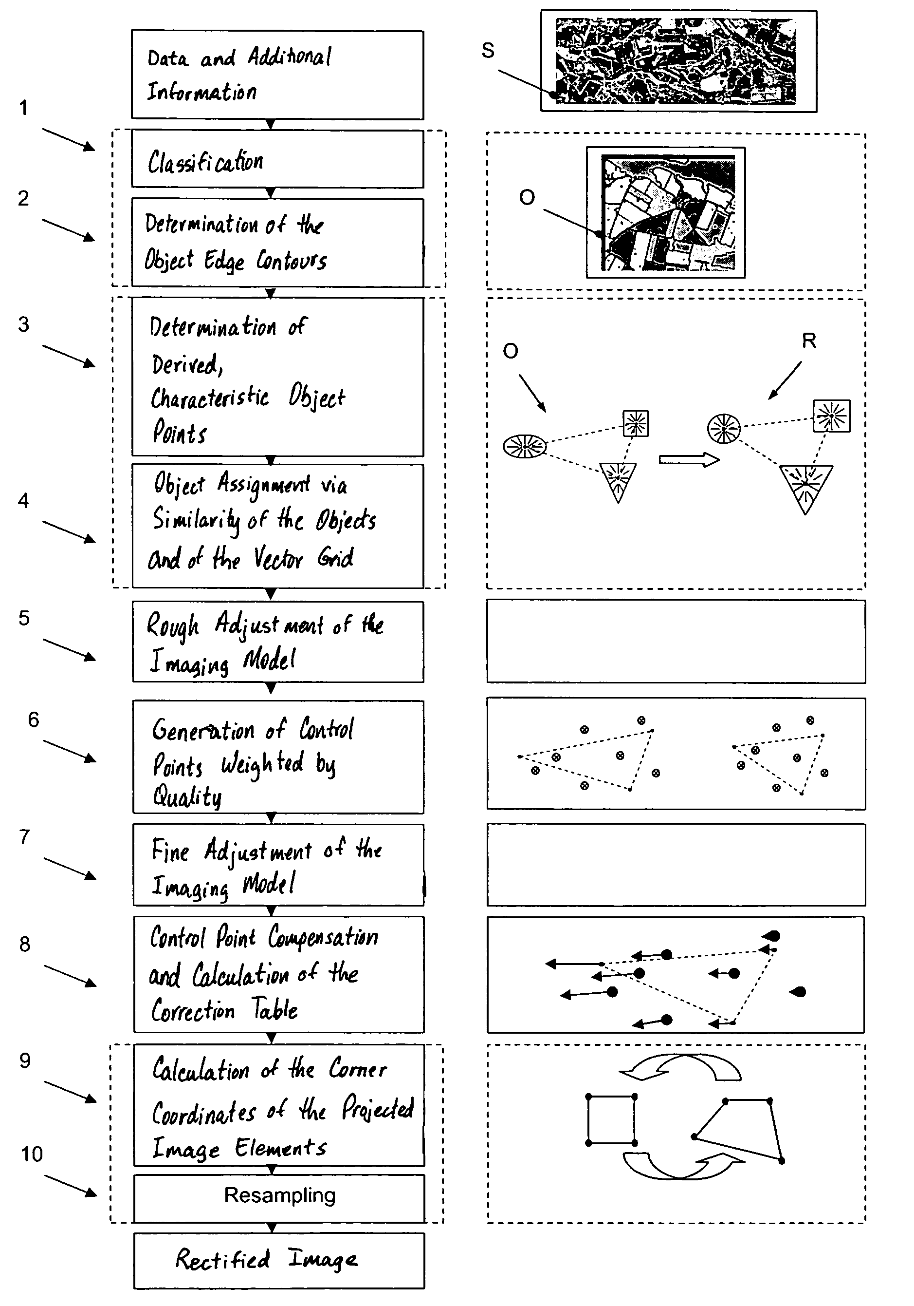
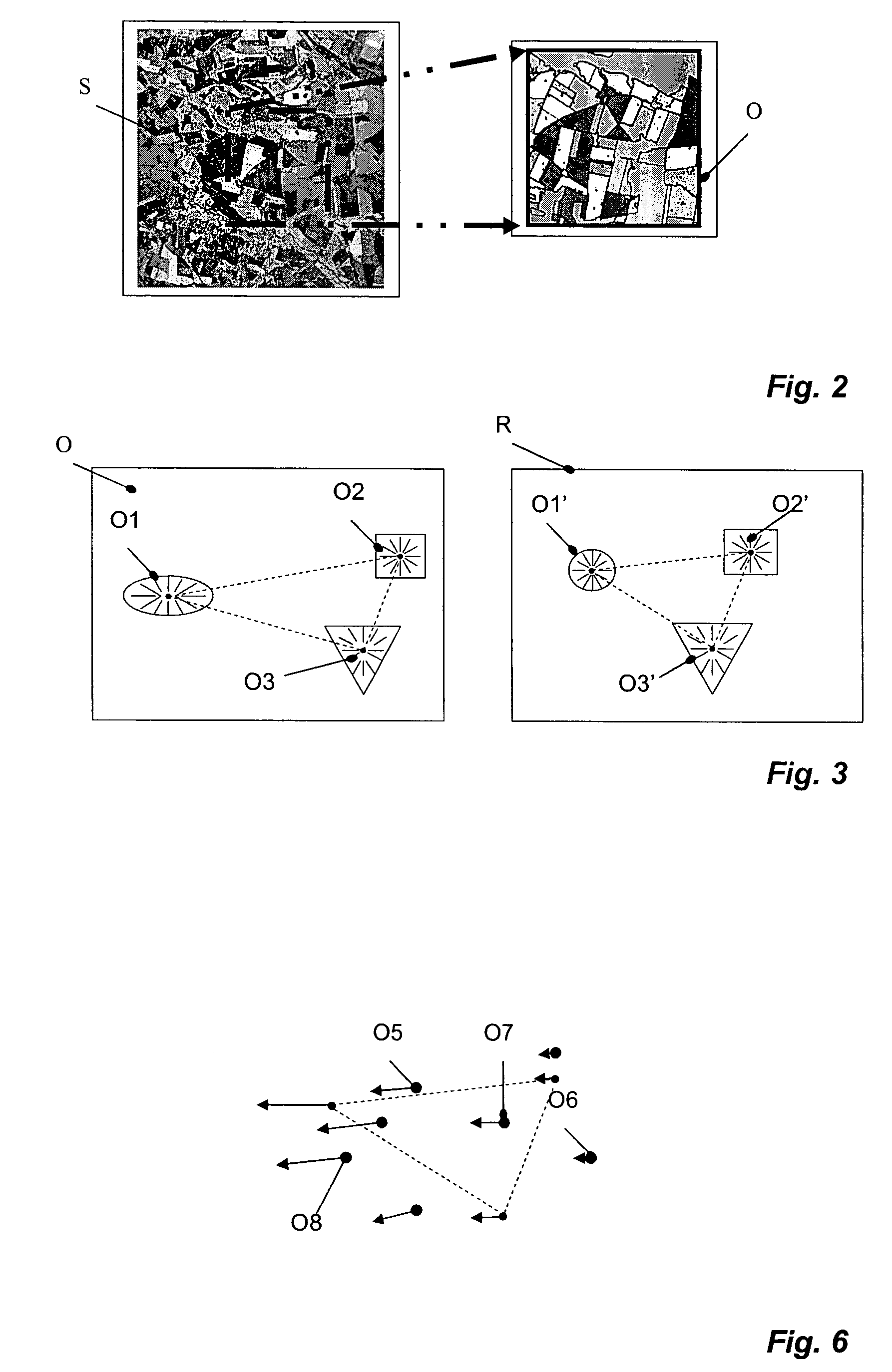
[0012]The problem is solved by a process for the automatic rectification of images, wherein at least one image is rectified by a mapping function onto a reference image, and at least some parameters of the mapping function are unknown. The process includes steps of extracting at least three objects from the image; determining at least three control points in the image, such that characteristic object points of the extracted objects are determined as control points; assigning the objects to objects in the reference image, such that assignment is made according to similarity between corresponding objects in the two images and / or on the basis of a vector
arid formed by connections between the characteristic object points; and selecting a suitable mapping function and / or adjusting parameters of the mapping function, whereby the mapping function is changed by changing the parameters in such a way that cumulative error in positional differences between control points and corresponding points in the reference image is minimized.
[0013]The problem is further solved by a device for performing the aforesaid steps. The device includes an extraction module for extracting at least three objects from the image; a control point determination module for determining at least three control points in the image, wherein characteristic points of the extracted objects are determined as control points; an object assignment module for assigning the objects to objects in the reference image, such that a correspondence between the objects in the two images is established according to at least one of a similarity between objects, a vector grid formed by connecting characteristic object points, and a selection module. The correspondence is established for at least one of selecting a suitable mapping function and adjusting parameters of the mapping function, whereby the mapping function is changed by changing the parameters in such a way that cumulative error in positional differences between control points and corresponding points in the reference image is minimized.
[0015]For the automatic rectification of an image onto a reference image, where at least some of the parameters of the mapping function for the rectification process are unknown, at least three objects are extracted from the image and at least three control points are determined. Characteristic points of the extracted objects are then determined as control points. The extracted objects are assigned to objects in the reference image, the objects of one image being assigned to those of the other on the basis of the similarity between the objects and / or on the basis of a vector grid, the vector grid being formed by connecting the characteristic object points. The parameters of the mapping function are adjusted and / or a suitable known mapping function is determined on the basis of the control points and the corresponding points in the reference image. The adjustment and / or determination is carried out in such a way that a minimum cumulative error is achieved for the positional differences between projected control points and the corresponding control points in the reference image. Mapping functions with fixed parameter sets are filed, for example, in a
database. An adjustment of this type is of interest when many mapping process of the same type are present. So that suitable objects can be chosen, it is advantageous for the objects to have conspicuous and unique forms, so that gross errors can be excluded. The reference image can be mapped in a known
map projection, or it can have an unknown mapping base. If the mapping base is known, the mapping function is taken from the mapping model. If the mapping base of the reference image is unknown, the mapping function will be an affine transformation. By adjusting the parameters to obtain the minimum cumulative error, the mapping function can be adjusted without precise knowledge of the mapping model and / or, if the mapping base is absent, without a mapping model at all.
[0017]In another embodiment, the positions of the control points obtained in the image to be rectified are determined more precisely by a comparison of the control point structures. It would be possible either to project parts of the control point structure of the image onto the reference image or to do the reverse. Image resolutions are preferably calculated for both image parts, and the less-resolved image part is projected onto the more highly resolved one. First, the gray-scale distribution or gray-scale distributions of the projected
image structure are adjusted to the associated control point structure in the image to be rectified and / or in the reference image. It is thus possible to rectify the differences that result, for example, from different lighting conditions during the recording of the image in question. Then the gray-scale values of the individual pixels in the control point structure or
image structure are determined, and the differences between adjacent pixels are found. These differences are compared with the differences between the corresponding pixels in the other structure, from which an error value is derived. Then the control point structure in the image to be rectified is shifted in the X or Y direction, and another error value is found. By the stepwise displacement of the control point structure in the X and Y directions, an error matrix is generated. The size of the individual steps is smaller than the dimension of the control point structure. The position of the control point structure that has the smallest error is identified as the best-adjusted position. Positions that have been determined in this way have high positional accuracy. As a result, the adjustment of the imaging parameters can be improved.
[0019]In another preferred embodiment, a rectification calculation is carried out which further reduces the residual error in the positional determinations. Here at least one vertical and / or one horizontal correction value is determined for each control point; these correction values embody the deviation of the value of the mapping function from the value of the compensating function at the site of the associated pixel for a projection using the best-adjusted mapping function. The correction values thus obtained can be stored in a correction table and used for further
processing. The best-adjusted mapping function is next determined. In many cases, however, a residual error of the best-adjusted mapping function in comparison with the function on which the mapping process is actually based is unavoidable and / or avoidable only with extreme effort. With the help of the correction function taken from the correction table, it is then possible to rectify an image with high quality even if the best-adjusted mapping function still contains residual error.

