Vacuum cleaner

Active Publication Date: 2008-04-15
ELECTROLUX HOME CARE PRODS
View PDF13 Cites 54 Cited by
  • Summary
  • Abstract
  • Description
  • Claims
  • Application Information

AI Technical Summary

Benefits of technology

[0026]Another disadvantage of known vacuum cleaners which can be used for both floor and above-floor cleaning is that each time the cleaner is required for above-floor cleaning, the user firstly has to locate and then connect a tool to the end of the hose before cleaning can commence. Thus, the cross-sectional area of the rigid tubular duct extending along the handle preferably increases substantially from said second air inlet at said first end of the handle towards said outlet disposed

Problems solved by technology

A disadvantage of this arrangement is that during conventional floor cleaning, the airflow thorough the cleaner is partially restricted by the elongate flexible hose, which is coiled for storage on the back of the cleaner.
The coiled length of hose is also susceptible to blockage.
A disadvant

Method used


Image

  • Vacuum cleaner
  • Vacuum cleaner
  • Vacuum cleaner

Examples


Example

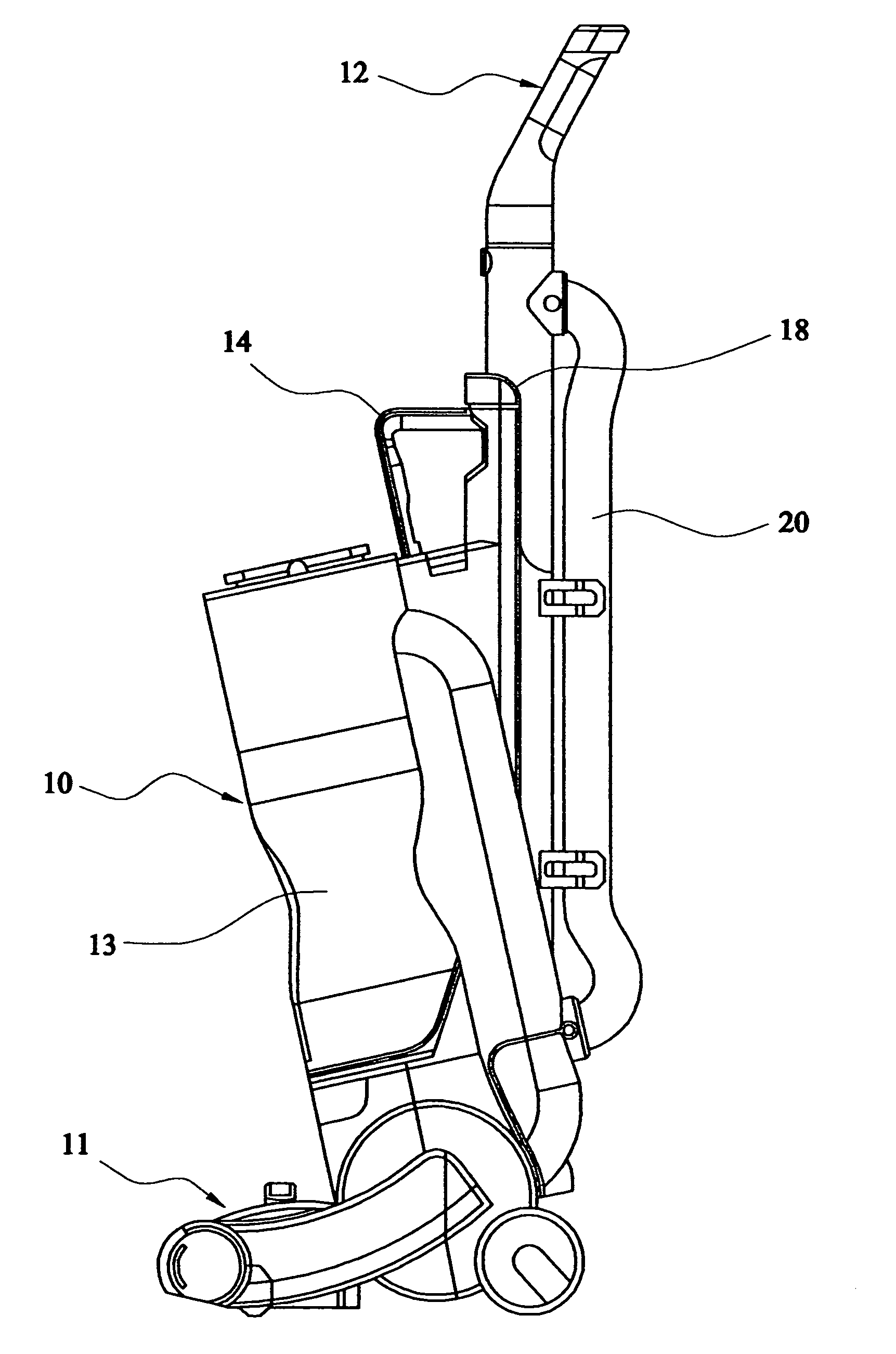
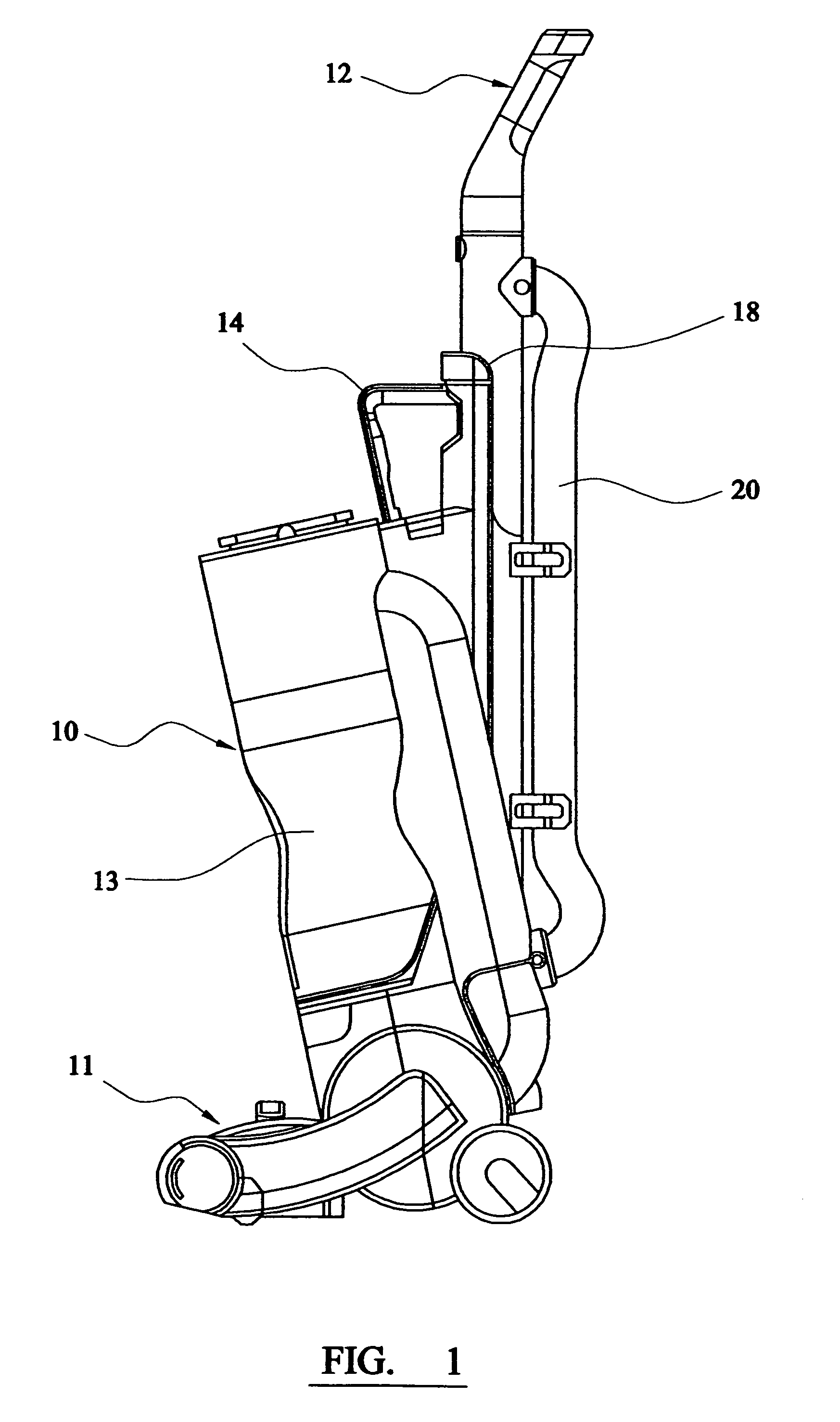
[0032]Referring to FIG. 1 of the drawings, there is shown an upright vacuum cleaner comprising a upright portion 10 pivotally connected at its lower end to a floor-engaging portion 11 for partial rotation forwardly and rearwardly about a transverse axis. The upright portion 10 encloses a motor / fan unit and comprises a detachable handle 12 at its upper end for propelling and guiding the cleaner over the surface being cleaned. The floor-engaging portion 11 incorporates a suction inlet and a conventional motor-driven rotating brush mounted across the inlet.

[0033]A cylindrical separation unit 13 for separating dirt and dust from the airflow is mounted to the front of the upright portion 10 of the cleaner. A further handle 14 for carrying the cleaner is provided on top of the upright portion 10 of the cleaner.

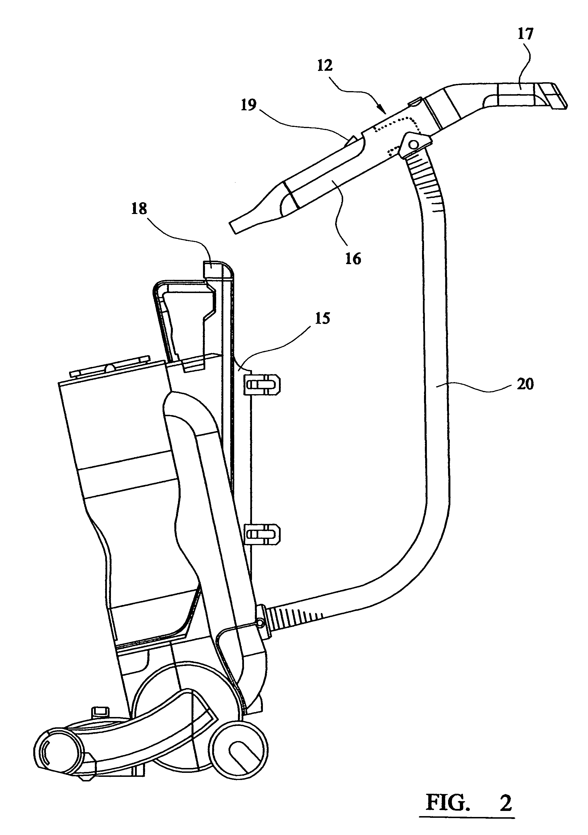
[0034]Referring to FIG. 2 of the drawings, the handle 12 for guiding and propelling the cleaner during floor cleaning comprises a tubular lower portion 16 and an upper portion 17 in...


PUM


Abstract

An upright vacuum cleaner comprises a body including a dust separator, a floor engaging head having a first dirty air inlet on its underside, a handle detachably mounted in a socket on the body and having a second dirty air inlet at its lower end, a flexible hose extending between the center of the handle and the body, a valve, and a valve actuator disposed in the socket for configuring the valve to connect the dust separator to the first or second inlets respectively when the handle is engaged and disengaged from the body. When engaged to the body, the upper end of handle is used to propel and guide the cleaner while suction is applied to the first dirty air inlet in the floor engaging head. Once detached, the handle is immediately ready for use as a tool for above-floor cleaning without the user having to manually divert the suction or fit cleaning tools.

Description

BACKGROUND OF THE INVENTION[0001]1. Field of the Invention[0002]This invention relates to a vacuum cleaner.[0003]2. Related Background Art[0004]Known vacuum cleaners are either of the so-called upright type or the so-called cylinder type. Upright vacuum cleaners comprise an upright portion pivotally connected at its lower end to a wheeled floor-engaging portion for partial rotation forwardly and rearwardly about a transverse axis. The upright portion encloses a motor / fan unit which draws air into a dust separation device through an inlet in the floor-engaging portion of the cleaner. A handle is provided at the upper end of the upright portion for pushing the cleaner to and fro. A motor-driven rotating agitator brush mounted across the inlet in the floor-engaging portion beats and sweeps the floor in the region of the airflow into the cleaner.[0005]Cylinder vacuum cleaners comprise a body which encloses a motor / fan unit which draws air into a dust separation device through an elongat...

Claims


Application Information

Patent Timeline
IPC IPC(8): A47L9/00A47L5/32A47L9/32
CPCA47L5/32A47L9/325
Inventor SKINNER MACLEOD, EUANRICHARDSON, ROSSHENDERSON, CHRISTOPHER RICHARD
Owner ELECTROLUX HOME CARE PRODS
Why Eureka
Try Eureka