
Brake pedal feel simulator

a simulator and pedal technology, applied in the field of can solve the problems of disorientation of operators and drawbacks of such brake pedal feel simulators, and achieve the effects of reducing the simulation force, improving the operator's ability to brake the vehicle, and reducing the resistance to translation of the brake pedal

Active Publication Date: 2008-04-15
CONTINENTAL AUTOMOTIVE SYST INC
View PDF13 Cites 27 Cited by
  • Summary
  • Abstract
  • Description
  • Claims
  • Application Information

AI Technical Summary

Benefits of technology

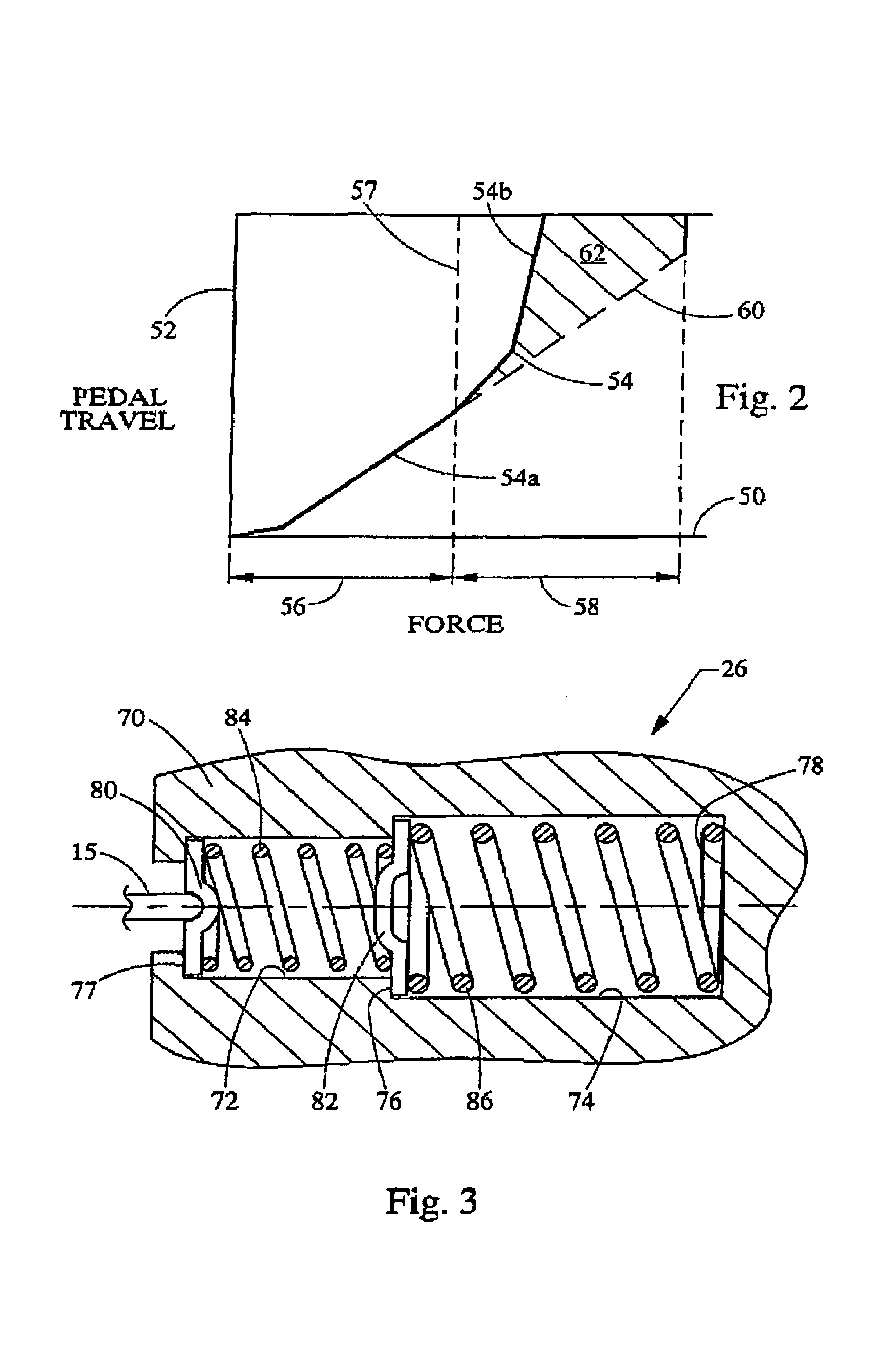
The present invention provides a brake pedal feel simulator that reduces the simulation force provided to the brake pedal during emergency or failed conditions. The simulator includes two springs with different spring rates. When a predetermined force level is achieved at the brake pedal and simulator, the spring rate provided by the simulator shifts to the second spring rate, reducing the resistance to translation of the brake pedal and improving the operator's ability to brake the vehicle. The second spring is pre-loaded to a predetermined force level, which is greater than the force required to begin loading the first spring. The predetermined force level is selected to be greater than or equal to a minimum brake pedal force achieved during an emergency braking condition or a non-assisted braking condition or a failed power condition. The brake pedal feel simulator may include a spring seat and a housing enclosing the springs. The springs may be selected from any known material or structure having spring properties, including compression springs, tension springs, and elastomeric springs.

Problems solved by technology

Since an electronic brake system may not have such hydraulic pressure at the brake pedal, the vehicle operator will not detect any countering force, which in turn can disorient the operator.
The Applicants have discovered a drawback to such brake pedal feel simulators in electronic brake systems which rely on brake pedal force as an element of actuating the wheel brakes.

Method used


Image

  • Brake pedal feel simulator
  • Brake pedal feel simulator
  • Brake pedal feel simulator

Examples


Embodiment Construction

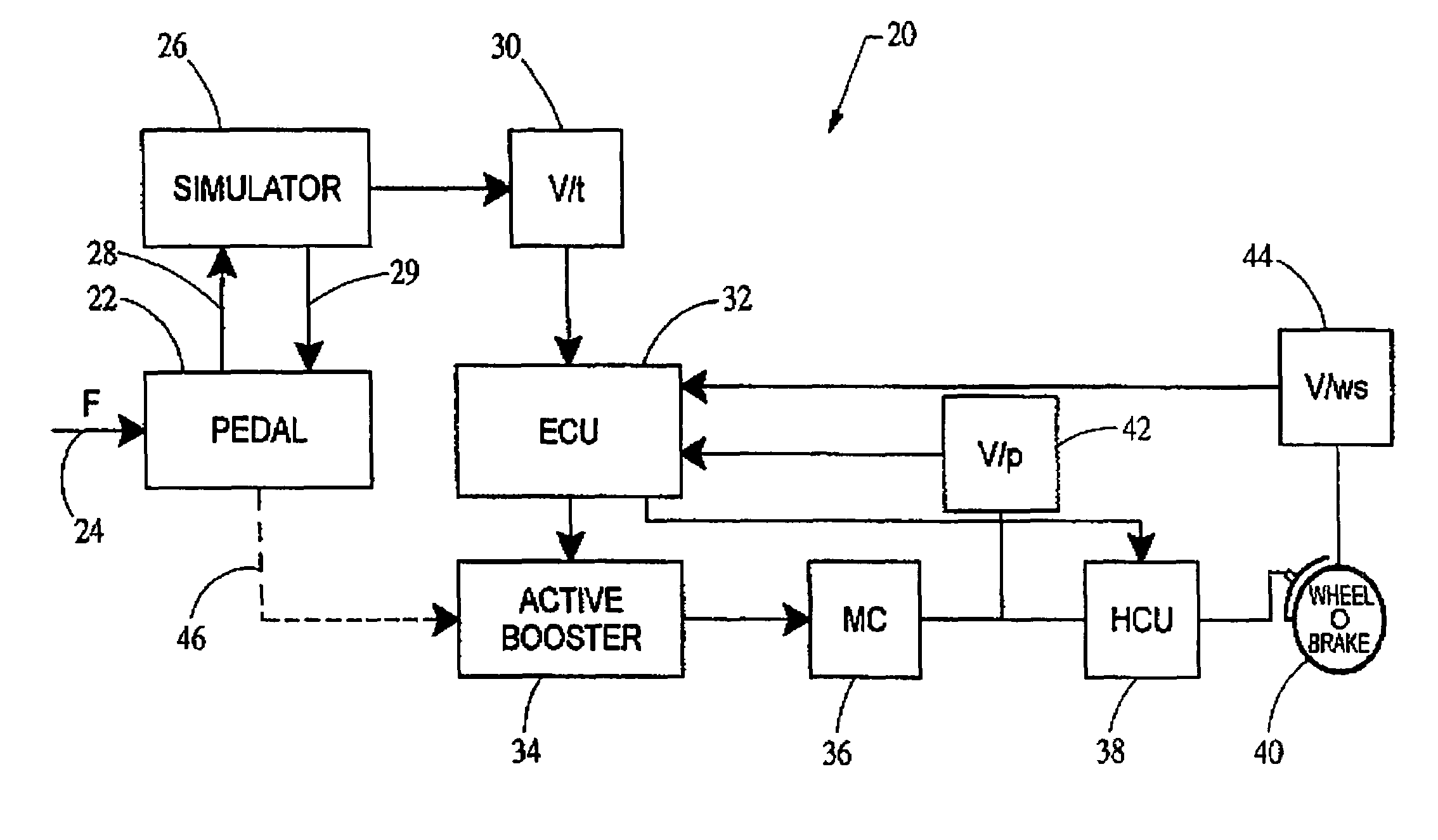
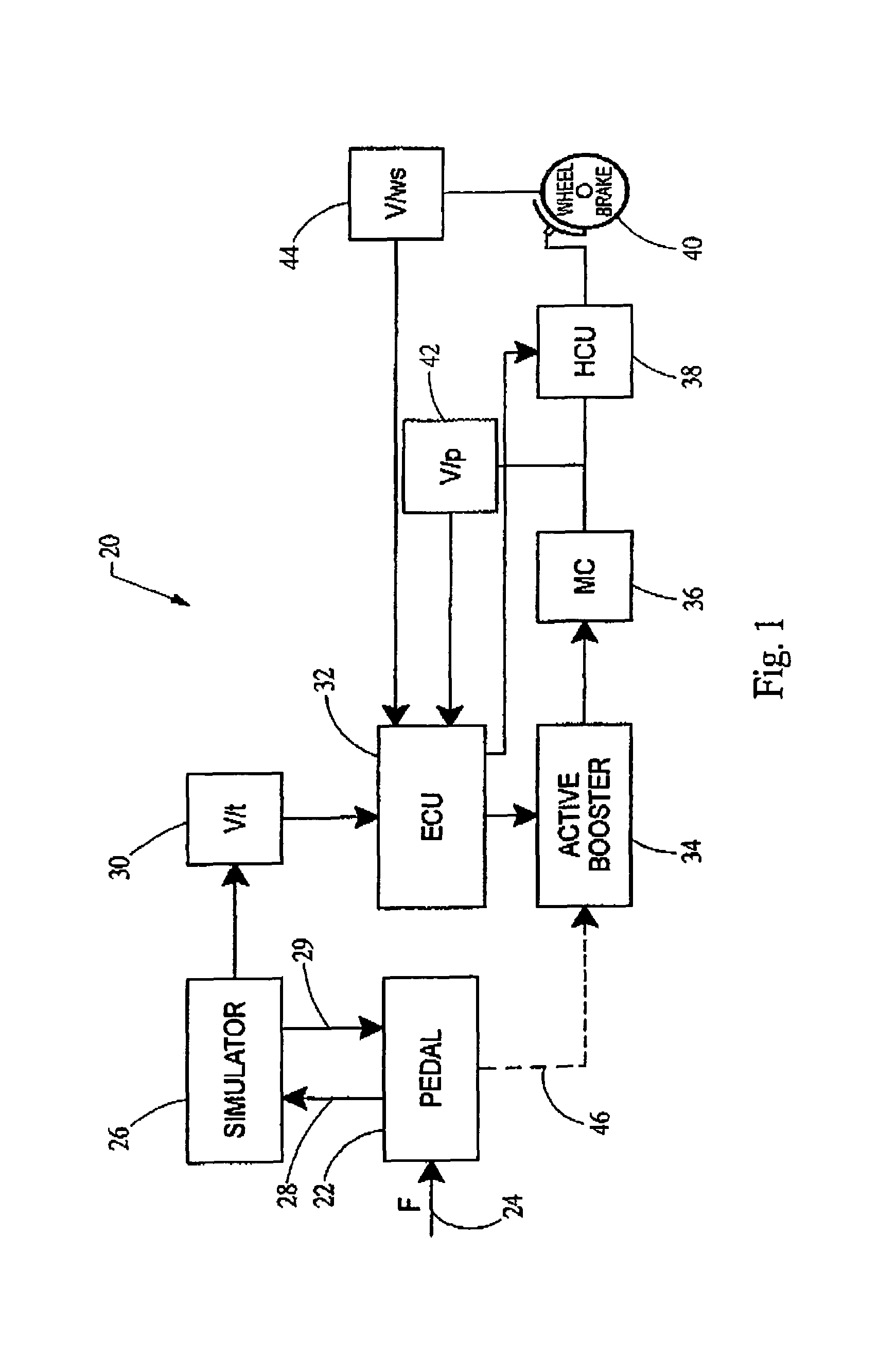
[0014]Turning now to the figures, FIG. 1 schematically depicts an electronic braking system 20 having a simulator 26 constructed in accordance with the teaching of the present invention. The braking system 20 generally includes a brake pedal 22 receiving an input force denoted by arrow 24 from the operator of the vehicle. The operator force 24 is transmitted through the pedal 22 to the simulator brake pedal feel simulator 26 which also transmits a simulation force 29 back to the brake pedal 22. A displacement sensor 30 is used to monitor pedal travel and transmits a corresponding signal to an electronic control unit 32 which represents the central control of the braking system 20. The electronic control unit 32 sends a control signal to an active booster 34, which in turn is mechanically linked to a master cylinder 36. The master cylinder 36 is hydraulically connected to the wheel brake 40 through a hydraulic control unit 38 and booster 34 which together regulate the braking force a...


PUM


Abstract

A brake pedal feel simulator is provided which reduces the simulation force provided to the brake pedal during emergency or failed conditions. The simulator generally comprises a first spring having a first spring rate and a second spring having a second spring rate. The second spring rate is selected to be lower than the first spring rate. When a predetermined force level is achieved at the brake pedal and simulator, the spring rate provided by the simulator shifts to the second spring rate. In this manner, the rate resistance to translation of the brake pedal is reduced, thereby improving the operator's ability to brake the vehicle.

Description

FIELD OF THE INVENTION[0001]The present invention relates generally to brake pedal feel simulators for providing a simulation braking force to a brake pedal of a motor vehicle, and more particularly relates to operation of such a brake pedal feel simulator during failed or emergency braking conditions.BACKGROUND OF THE INVENTION[0002]Electronic brake systems, such as so-called “brake by wire” systems, are increasingly being integrated into or replacing conventional hydraulic brake systems of motor vehicles including passenger cars, SUV's and light trucks. Such electronic brake systems are preferable because they reduce the mass of the system, provide greater ability to integrate the system into the vehicle's other electronic circuits and controls, and are suited for use with sophisticated brake control systems.[0003]During depression of the brake pedal by a vehicle operator in a conventional hydraulic braking system, the hydraulic fluid will exert a reaction force back on the brake ...

Claims


Application Information

Patent Timeline
Patent Type & Authority Patents(United States)
IPC IPC(8): B60T8/34
CPCB60T8/326B60T8/4077
Inventor YOUNG, KENT RANDOLPHAGNEW, DAVID LESLIE
Owner CONTINENTAL AUTOMOTIVE SYST INC
Learn More