Method of fixing an optical element and method of manufacturing optical module including the use of a light transmissive loading jig

a technology of light transmissive loading and fixing elements, which is applied in the direction of optical elements, discharge tubes/lamp details, instruments, etc., can solve the problems of deformation of the lens surface affecting the quality increasing the temperature of the optical element, so as to suppress the effect of temperature rise of the optical elemen

Active Publication Date: 2008-04-15
KONICA MINOLTA INC
View PDF2 Cites 46 Cited by
  • Summary
  • Abstract
  • Description
  • Claims
  • Application Information

AI Technical Summary

Benefits of technology

[0009]In view of the above problems of the aforesaid conventional art, an object of the present invention is to provide a method of fixing an optical element and a method of manufacturing an optical module, wherein a thickness of the hardened optical-curing adhesive can be made even with a simple configuration and an adverse effect such as a temperature rise in the optical element can be suppressed even if UV is radiated to the optical element for adhesion fixing by the optical-curing adhesive.

Problems solved by technology

An experimental test performed by inventors of the present invention clarified that it is necessary to radiate UV for a certain period of time to harden UVA, however on the other hand, if UV light is irradiated to the optical element for more than 10 sec, a temperature of the optical element will increase considerably and there is caused a bad effect such as deformation of the lens surface of the optical element, in case an optical element such as a lens is made of resin material.
Also the structure to arrange the weight and the optical fibers is complicated, thus, the process of hardening adhesive is time-consuming, which lowers productivity.

Method used


Image

  • Method of fixing an optical element and method of manufacturing optical module including the use of a light transmissive loading jig
  • Method of fixing an optical element and method of manufacturing optical module including the use of a light transmissive loading jig
  • Method of fixing an optical element and method of manufacturing optical module including the use of a light transmissive loading jig

Examples


first embodiment

The First Embodiment

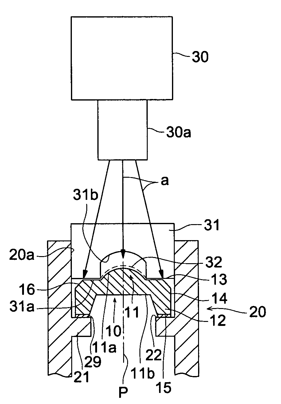
[0041]FIG. 1 is a vertical cross sectional view of essential portion showing a lens fixing structure, an UV light source, and a loading jig to explain an optical element fixing method of the first embodiment.

[0042]In the lens fixing structure in FIG. 1, lens 10 is bonded and fixed on inner surface 20a of cylindrical lens barrel 20.

[0043]Lens 10 is a plastic lens made of a resin for a optical element having lens section 11 provided with lens function, peripheral section 13 which is located at an outer circumference of lens section 11 and extended to outermost circumference 14 of lens 10 and mounting section 12 projecting from peripheral section 13 in a direction almost parallel to the optical axis p. Lens 11 has a convex section 11a with light axis p as a center and flat surface 11b on the reverse side of convex section 11a is extended from lens section 11 to a part of peripheral section 13. Peripheral section 13 and mounting section 12 can configure stress relief...

second embodiment

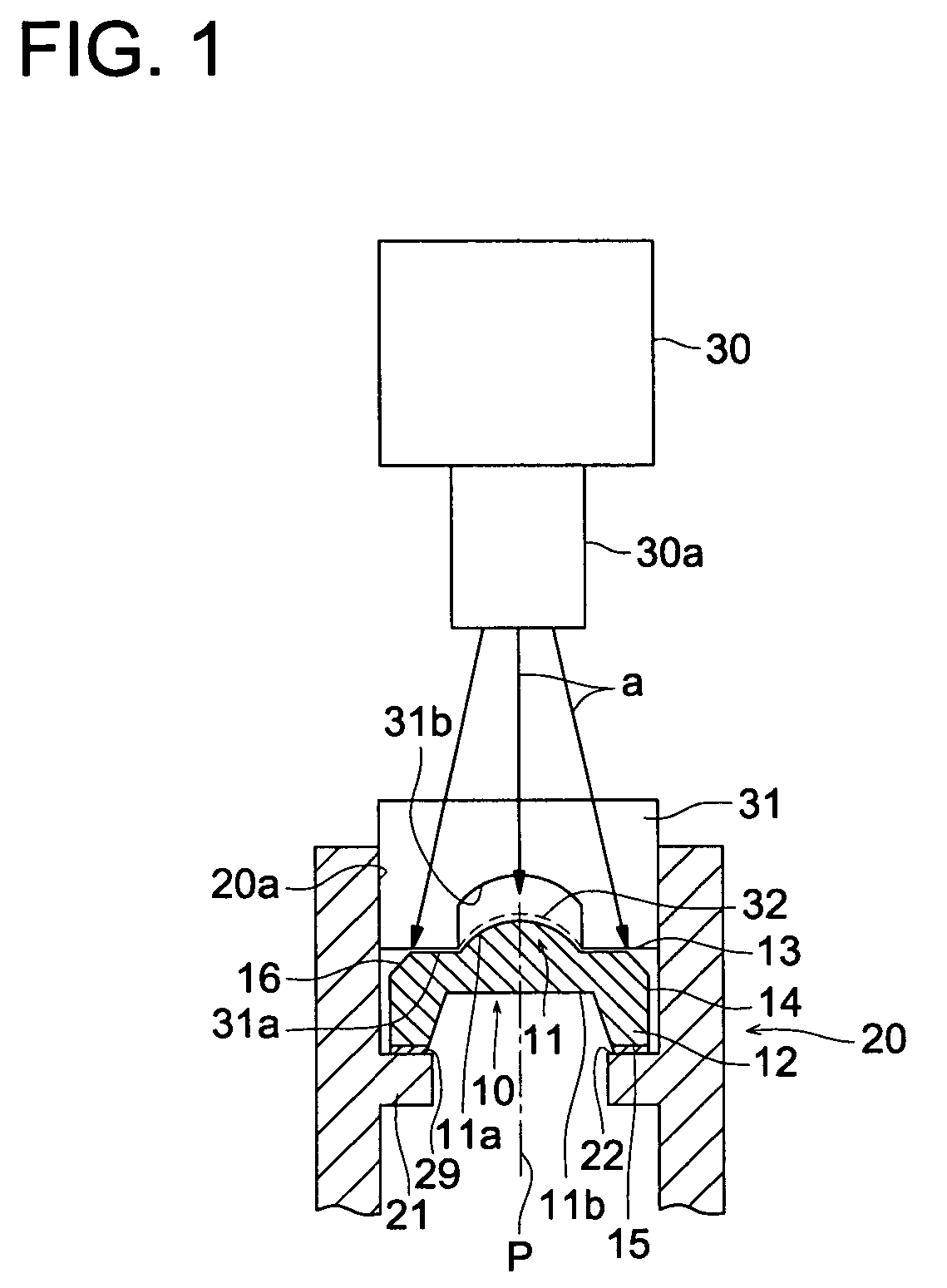
[0058]FIG. 2 to FIG. 5 are vertical cross-sectional views of essential portions showing schematically the lens fixing structures and the loading jigs for explaining fixing methods of each optical element of the second embodiment.

[0059]In the optical element fixing method of the second embodiment, the loading jig is made of a light-transmissive material, and UV is radiated while applying a load in a direction of thickness of adhesive through the lens by the loading jig. Meanwhile, the lenses to be adhesively fixed in

[0060]FIG. 2 to FIG. 4 are almost the same as lens 10 in FIG. 1, so that the same portions are given the same symbols and descriptions of them are omitted.

[0061]An example shown in FIG. 2 is a lens fixing structure in which cylindrical lens barrel 40 has retaining section 41 which is protruded to be in a collar shape in a direction perpendicular to optical axis p at lower part, and mounting surface 15 of mounting section 12 of lens 10 adhesively fixed to collar-shaped ret...

third embodiment

The Third Embodiment

[0079]FIG. 6 is a vertical cross-sectional view of essential portion schematically showing a lens fixing structure, a loading jig, a nozzle of UV light source and a positioning member to explain an optical element fixing method of the third embodiment.

[0080]An example of FIG. 6 is to align the nozzle 61 of the UV light source with lens barrel 40, lens 10 and loading jig 45 when the lens structure in FIG. 3 is realized by the loading jig.

[0081]As FIG. 6 shows, positioning member 62 is formed in a cylindrical shape and has collar-shaped placing section 62a which is projecting on the bottom. Also, the UV light source has nozzle 61 having inner hole 61a through which UV is radiated in UV radiation direction b, and the end nozzle 61 is inserted from upper side of the drawing into inner surface 62b of positioning member 62.

[0082]As FIG. 6 shows, while positioning member 62 is placed stably on workbench 65 by placing section 62a, lens barrel 40 is arranged in inner surf...


PUM


Abstract

In the optical element fixing method, when optical element 10 is adhesively fixing member 20 by using the optical-curing adhesive, the optical-curing adhesive is applied on at least one of the adhesion sections of the optical element and the adhesive section of the fixing member, and the optical-curing adhesive is irradiated with the light from the light source through the loading jig while the load is being applied to the adhesion fixing section through loading jig 31 made of light-transmissive material.

Description

[0001]This application is based on Japanese Patent Application No. 2005-191609 filed on Jun. 30, 2005, in Japanese Patent Office, the entire content of which is hereby incorporated by reference.BACKGROUND OF THE INVENTION[0002]The present invention relates to a method of fixing an optical element wherein the optical element is bonded and fixed on a fixing member by optical-curing adhesive, and to a method to manufacture an optical module.[0003]In the past, to bond and fix an optical element such as a pick up lens and a micro lens used for an optical communication module on a fixing member such as a lens barrel, after applying UV curing adhesive, UV was radiated from a light source to the UV curing adhesive (hereinafter called UVA) so as to fix the optical element on the fixing member. For example, as shown in FIG. 14, to fix lens 100 on lens barrel 200, UVA was applied on collar-shaped retaining surface 220 in metal lens barrel 200 and adhesive layer 290 is formed by radiating UV fr...

Claims


Application Information

Patent Timeline
Patent Type & Authority Patents(United States)
IPC IPC(8): H01J5/02G02B7/02
CPCG02B7/025G02B27/62
Inventor MITSUGI, NAOKIMIYAKOSHI, HIROSHISHIBUYA, YOSHIKI
Owner KONICA MINOLTA INC
Why Eureka
Try Eureka