Wide-angle variable focal length lens system

a lens system and variable focal length technology, applied in the field of flexible lens systems, can solve the problems of severe optical distortion, limited application of liquid crystal lenses, and difficulty in employing mechanical focusing mechanisms

Inactive Publication Date: 2008-04-15
LOUISIANA TECH UNIV RES FOUND A DIV OF LOUISIANA TECH UNIV FOUND
View PDF16 Cites 123 Cited by
  • Summary
  • Abstract
  • Description
  • Claims
  • Application Information

AI Technical Summary

Problems solved by technology

These systems with lenses and mirrors as conventional optical elements of fixed focal length use focusing mechanisms which are complicated and consist of many moving parts such as gears, motors and sliders to image a moving object or objects with high irregular shape.
These mechanical focusing mechanisms become particularly difficult to employ when dealing with microlens systems for micro-electrical mechanical sys

Method used


Image

  • Wide-angle variable focal length lens system
  • Wide-angle variable focal length lens system
  • Wide-angle variable focal length lens system

Examples


example 1

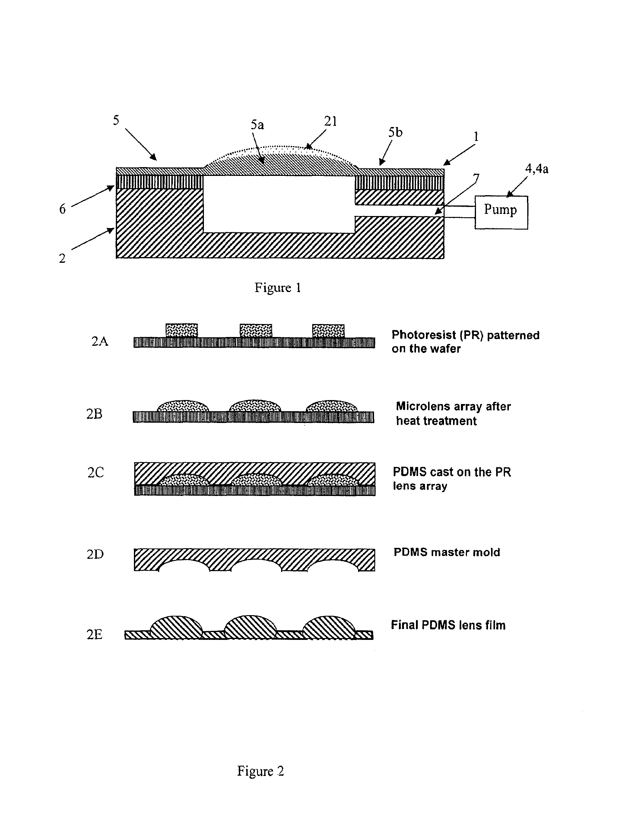
[0082]A flexible PDMS lens array was fabricated using the photoresist thermal treatment process described above in reference to FIG. 2. The photoresist material was AZ 100XT because the thickness of a single layer AZ 100XT can reach 50 μm. Two spin-coated photoresist layers are prepared which made the total thickness of the photoresist layer about 100 μm. Cylinders shapes are then formed in the photoresist using convention lithography techniques. These cylinders were thermally treated on a hot plate starting at 75° C. and gradually increasing the temperature. After reaching 120° C., the photoresist cylinders began to melt and reflow to form a spherical structure. The total reflow duration was 60 seconds. SEM images of the reflowed photoresist structures showed well formed 1500 μm diameter photoresist microlens structures which provided a mother mold for the microlens.

[0083]Next, the photoresist microstructure was transferred to a PDMS master by the casting method described above. PD...

example 2

[0093]A circular diaphragm actuator such as shown in FIG. 17 was designed. The actuator was made of transparent PDMS in order to not block light rays passing through the lens. Compliant, circular electrodes were fabricated on each side of PDMS film. The outside edge of the thin film was fixed tightly to prevent any movement. After applying the voltage on the electrodes, the thin film could be deformed in the central non-electrode part.

[0094]A mask for a circular actuator array was designed for a 4-inch substrate as suggested by FIG. 18. For a single actuation unit, the central transparent part was for a fabricated lens that was 3 mm in diameter. The compliant concentric circular electrodes were 3 mm from ID to OD. The actuator array was a 4×4 configuration of single units with connections to each other. After construction of the actuator devices, this pattern could be easily sectioned into small pieces for testing of either single unit actuators or different sized arrays of actuator...

example 3

[0108]Materials comprising various amount of (a) poly-dimethylsiloxane (PDMS) (Vinyl-addition silicone) as matrix, (b) Methacryloxypropyl Terminated PolyDimethylsiloxanes as photo-sensitive macromer, (c) a UV photoinitiator, 2-Hydroxy-2-methyl-1-phenyl-1-propanone (Ciba Darocur 1173), (d) a crosslinker (Gelest HMS-301), and (e) a Pt initiator for Vinyl-addition silicone cure (SIP6830.3), were made and tested. The first four components (a, b, c & d) were blended together initially. PDMS with the crosslinker HMS-301 was polymerized by addition of platinum catalyst as an initiator. PDMS was the polymeric matrix while the macromer and Darocur 1173 together formed the photo-sensitive macromer composition. Table 5 shows the samples' preparation and testing.

[0109]

TABLE 5Material composition for making GRIN lensesDiverging GRIN LensConverging GRIN LensPhotoinitiatorInitiatorMatrixMacromerMatrixMacromerCrosslinkerDarocur 1173Platinum CatalystPDV-0325SIB 1402.0PDV-1625SIB 1400.0HMS-301 (wt %)...


PUM


Abstract

A variable focal length microlens system having a base section with a fluid chamber and a fluid pressurization mechanism. A flexible, substantially transparent polymer lens section is fixed above the fluid chamber and the lens section has a curvature providing an initial focal point when in an unstrained state. The fluid chamber is substantially sealed and the fluid pressurization mechanism includes a flexible wall in the base section. The flexible wall may be displaced by magnetic activation, PZT activation of another activating mechanism.

Description

[0001]This application claims the benefit under 35 USC §119(e) to U.S. Provisional Application No. 60 / 567,274 filed Apr. 30, 2004, which is incorporated by reference herein in its entirety.[0002]The invention described herein was made with support of the U.S. Government, and the U.S. Government may have certain rights in the invention as provided for by the terms of Grant Nos. 32096756141 and BAA 01-42-#427 awarded by the Defense Advanced Research Projects Agency.FIELD OF THE INVENTION[0003]The present invention relates to flexible lens systems, in particular lens systems wherein certain optical parameters are selectively adjustable.BACKGROUND OF THE INVENTION[0004]Optical systems often require variable focal length to allow the field of view (FOV) or the magnification to be altered. These systems with lenses and mirrors as conventional optical elements of fixed focal length use focusing mechanisms which are complicated and consist of many moving parts such as gears, motors and slid...

Claims


Application Information

Patent Timeline
IPC IPC(8): G02B1/06G02B3/12
CPCG02B1/06G02B3/14G02B15/00
Inventor FANG, JICHEN, JACKIEWANG, WEISONGVARAHRAMYAN, KODYGUNASEKARAN, R. ALFREDAGARWAL, MANGILAL
Owner LOUISIANA TECH UNIV RES FOUND A DIV OF LOUISIANA TECH UNIV FOUND
Why Eureka
Try Eureka