Structure for collecting scattered electrons

a technology of electrons and structures, applied in the field of electron collectors, can solve the problems of x-ray tube heat up, high thermal stress on x-ray tube components, and additional thermal heating of x-ray tubes

Inactive Publication Date: 2008-04-15
GENERAL ELECTRIC CO
View PDF24 Cites 8 Cited by
  • Summary
  • Abstract
  • Description
  • Claims
  • Application Information

AI Technical Summary

Problems solved by technology

In general, this thermal energy from the hot anode target is radiated to various components within the x-ray tube's vacuum vessel and thereby causes the x-ray tube to heat up.
Furthermore, some of the electrons in the electron beam backscatter from the anode target and impinge on these same components within the vacuum vessel, thereby causing additional thermal heating of the x-ray tube.
As a result of the elevated temperatures caused by the cumulative effects of such thermal energies, the x-ray tube's components are subjected to high thermal stresses that are sometimes undesirable for proper operation of the x-ray tube itself.
In general, the production of such off-focal x-ray radiation tends to degrade x-ray imaging quality if it is allowed to exit the vacuum vessel's x-ray transmissive window.
Since the production of x-rays in a conventional x-ray tube is somewhat inherently an energy-inefficient process, the various components within such an x-ray tube typically operate at very high temperatures.
During operation of the x-ray tube, however, the performance of the cooling fluid may be degraded over time by excessively high temperatures that cause the fluid to boil at the interface between the fluid and the outer surface of the vacuum vessel or vacuum vessel's transmissive window.
When the cooling fluid is caused to boil in this manner, large bubbles may form within the fluid that undesirably facilitate high-voltage arcing across the fluid, thus degrading the insulating capability of the fluid.
Furthermore, the bubbles may give rise to x-ray image artifacts that produce low-quality images.
In addition to facilitating arcing, excessively high temperatures in an x-ray tube can also decrease the useful life of the tube's transmissive window, as well as other tube components.
Because of its conventionally close proximity to an electron beam's focal spot on the anode's target surface during tube operation, the x-ray transmissive window is subjected to very high heat loads resulting from thermal radiation and backscattered electrons.
In general, the high heat loads in an x-ray tube cause very large and cyclic stresses in the transmissive window and can lead to premature failure of the window and its hermetic seal(s).
Furthermore, since direct contact of the window (when excessively hot) with the cooling fluid can cause the fluid to boil as it flows over the window, degraded hydrocarbons from the fluid are sometimes apt to deposit on the window's outer surface, which can undesirably reduce x-ray imaging quality.

Method used


Image

  • Structure for collecting scattered electrons
  • Structure for collecting scattered electrons
  • Structure for collecting scattered electrons

Examples


Embodiment Construction

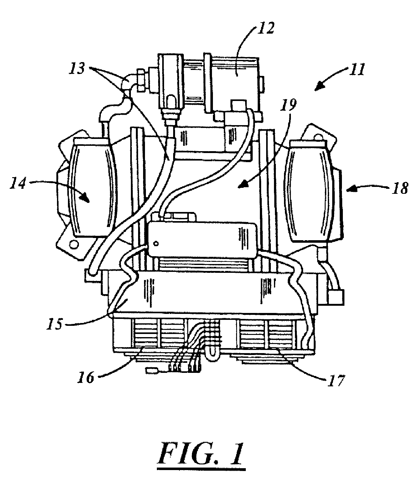
[0023]FIG. 1 illustrates a plan (i.e., top) view of a largely conventional x-ray system 11. As shown, the x-ray system 11 generally includes an anode end 14, a cathode end 18, and a center section 19. The center section 19 is situated between both the anode end 14 and the cathode end 18 and contains an x-ray tube 20 that serves to generate x-rays.

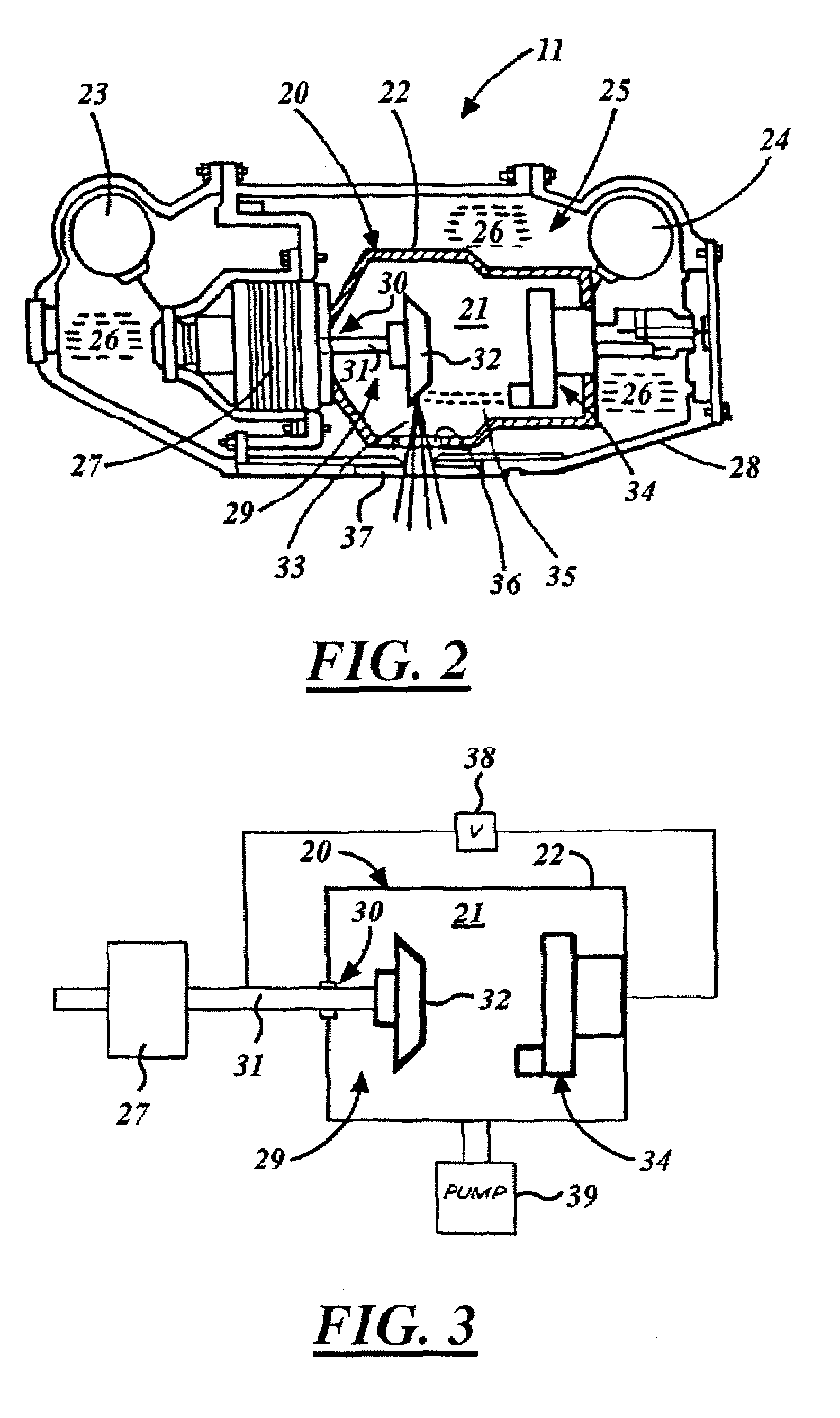
[0024]FIG. 2 illustrates a sectional side view of the x-ray system 11 depicted in FIG. 1. As shown in FIG. 2, the x-ray tube 20 in the system 11 largely includes a vacuum vessel 22 that is situated in a chamber 25 defined within a casing 28. The vacuum vessel 22 is constructed to endure very high temperatures and includes x-ray transmissive materials such as, for example, glass or Pyrex, and may even include sections of non-transmissive materials such as stainless steel or copper. The casing 28, on the other hand, may include, for example, aluminum and may also be lined with lead to block the passage of x-rays therethrough. Per convention, ...


PUM


Abstract

A structure for collecting scattered electrons within a substantially evacuated vessel containing both an electron-emitting cathode and an electron-attracting anode is disclosed herein. The electron-collecting structure includes a two-sided first plate, a two-sided second plate, a fluid inlet, and a fluid outlet. The first plate is both electrically conductive and thermally emissive and is mountable within the vessel so that its first side at least partially faces the anode. The second plate is also thermally emissive and has a first side that is substantially conterminous with the second side of the first plate. Furthermore, the second plate additionally has an internal conduit for conveying a heat-absorbing fluid within. Both the fluid inlet and the fluid outlet are in fluid communication with the conduit in the second plate. During operation, the structure is able to attract scattered electrons and transfer thermal energy attributable to the electrons away from the structure.

Description

FIELD OF THE INVENTION[0001]The present invention generally relates to electron collectors and more particularly relates to structures for collecting scattered electrons within, for example, a substantially evacuated vessel.BACKGROUND OF THE INVENTION[0002]Electron beam generating devices, such as x-ray tubes and electron-beam welders, generally operate in high-temperature environments. During operation of an x-ray tube, for example, the primary electron beam generated by its cathode deposits a very large heat load on its anode target such that the target glows red-hot. Typically, less than 1% of the primary electron beam's energy is converted into x-rays, while the balance of its energy is converted into thermal energy. In general, this thermal energy from the hot anode target is radiated to various components within the x-ray tube's vacuum vessel and thereby causes the x-ray tube to heat up. Furthermore, some of the electrons in the electron beam backscatter from the anode target ...

Claims


Application Information

Patent Timeline
Patent Type & Authority Patents(United States)
IPC IPC(8): H01J35/10H01J35/12
CPCH01J35/16H01J2235/1216H01J2235/1237H01J2235/125H01J2235/1262H01J2235/1283H01J2235/168
Inventor SUBRAYA, MADHUSUDHANA T.HEBERT, MICHAEL SCOTTSTEINLAGE, GREGORY ALAN
Owner GENERAL ELECTRIC CO
Why Eureka
Try Eureka