DNA microarray image analysis system

a microarray and image analysis technology, applied in image enhancement, fluorescence/phosphorescence, instruments, etc., can solve the problems of reproducibility and quantitativeness, and the spot coordinates of similar spots in a block are prone to have similar statuses, so as to increase the ability of the feed-forward neural network

Inactive Publication Date: 2008-04-15
HITACHI SOFTWARE ENG
View PDF3 Cites 2 Cited by
  • Summary
  • Abstract
  • Description
  • Claims
  • Application Information

AI Technical Summary

Benefits of technology

[0020]The feed-forward neural network configured thus is made storable and readable so as to increase the ability of the feed-forward neur

Problems solved by technology

However, a flag is manually set by changing the status of a spot lacking reproducibility and quantitativeness.
Further, according to the c

Method used


Image

  • DNA microarray image analysis system
  • DNA microarray image analysis system
  • DNA microarray image analysis system

Examples


Embodiment Construction

[0029]An embodiment of the present invention will be specifically described below in accordance with the accompanying drawings.

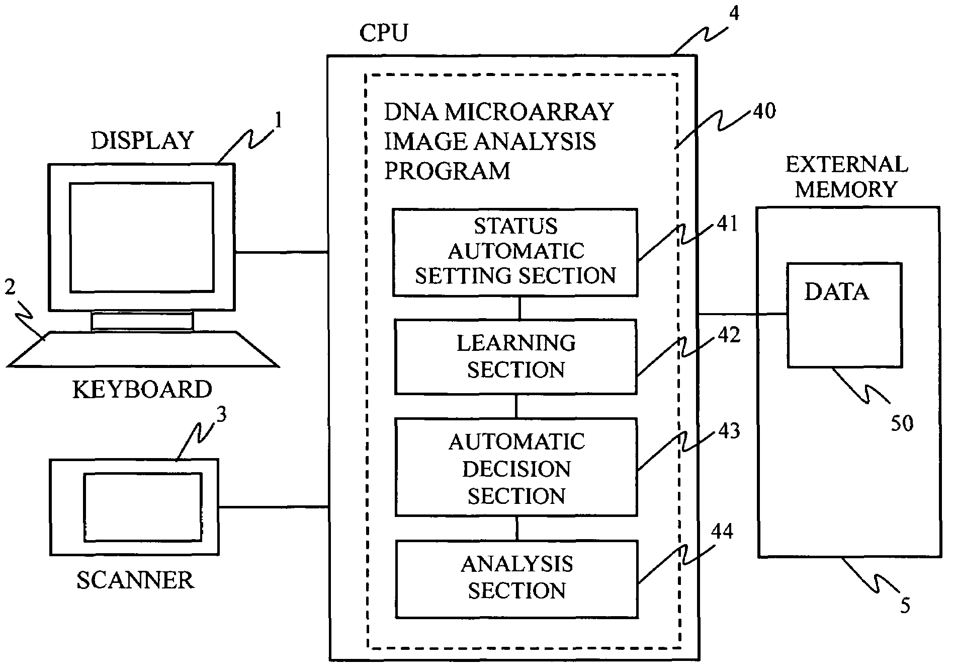
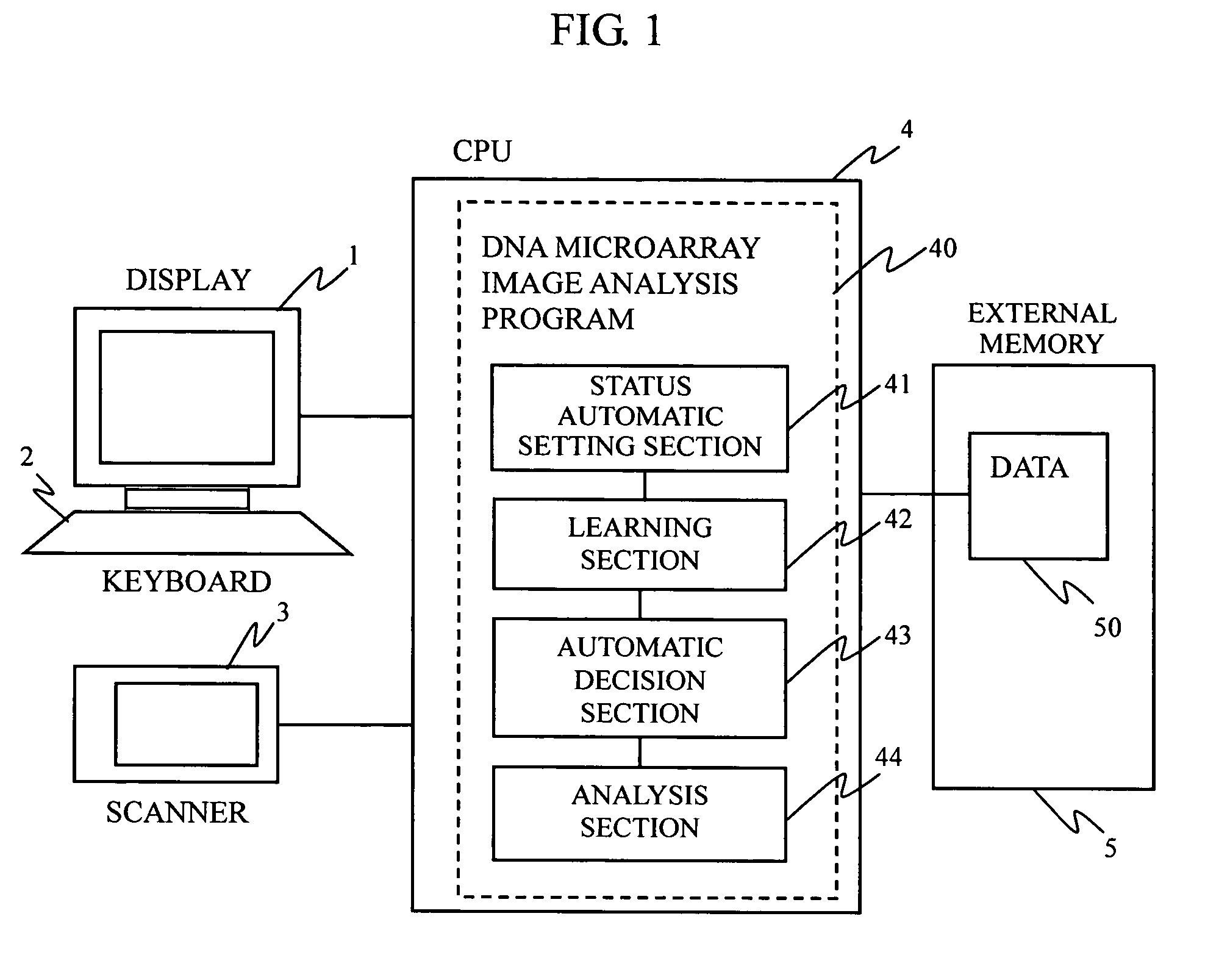
[0030]FIG. 1 is a diagram showing an example of the configuration of a DNA microarray image analysis system according to the present invention. The system is broadly constituted of input / output devices including a display 1, a keyboard 2, and a scanner 3, a CPU 4, and an external memory 5. A DNA microarray image analysis program 40 is stored in the memory region of the CPU 4. The DNA microarray image analysis program 40 is composed of a status automatic setting section 41 for automatically setting one of a plurality of statuses which can be arbitrarily set by the user for each spot region of a DNA microarray image after hybridization, a status learning section 42 for learning the set status by using a pixel value of each spot region and storing the learning results in the external memory 5, an automatic decision section 43 for performing automatic decision b...


PUM


Abstract

In a microarray image analysis system, when one of a plurality of statuses is set for a spot of a microarray by the user, the status of a similar spot is automatically determined. In a microarray image, the user determines a status of a spot, the pixel value matrix of an image in a spot region is learned by a neural network, a vertically and horizontally symmetrical image and an image rotated about the center of the region are formed and are learned by the neural network, and the neural network formed by repeating these steps is used for automatically recognizing the status of an undecided spot.

Description

BACKGROUND OF THE INVENTION[0001]1. Field of the Invention[0002]The present invention relates to a pattern recognition system for handling an image of a DNA microarray and particularly relates to an image analysis system for a Stanford type microarray having a plurality of blocked spots.[0003]2. Background Art[0004]Stanford type microarrays are available which have a plurality of blocked spots. For example, one microarray has 4×8 blocks each of which is constituted of X×Y spots. After a specimen is brought into contact with the microarray, a fluorescent intensity of each spot is optically measured. In the optical measurements, each spot is divided into N×M pixels and the pixels are sequentially or simultaneously measured. Since a quite a number of measurements are performed with a massive amount of data, microarray image analysis systems are developed to perform statistical analysis on obtained data.[0005]For example, as to automatic recognition of the position and size of a spot in...

Claims


Application Information

Patent Timeline
IPC IPC(8): G06K9/00G01N21/64G01N21/78G01N33/483G01N33/53G01N37/00G06T7/00G16B25/30G16B40/20
CPCG06F19/20G06K9/00G06T7/0012G06T2207/30072G06F19/24G16B25/00G16B40/00G16B25/30G16B40/20G06F18/00
Inventor MORI, ATSUSHI
Owner HITACHI SOFTWARE ENG
Why Eureka
Try Eureka