
Apparatus and method for improving efficiency of power amplifier operating under large peak-to-average power ratio

a power amplifier and efficiency technology, applied in the field of power amplifiers, can solve the problems of increasing manufacturing costs, increasing error rate and spectral regrowth, and inefficient power amplifiers, and achieve the effect of improving the efficiency of power amplifiers and large peak-to-average power ratios

Inactive Publication Date: 2008-04-15
SAMSUNG ELECTRONICS CO LTD
View PDF13 Cites 8 Cited by
  • Summary
  • Abstract
  • Description
  • Claims
  • Application Information

AI Technical Summary

Benefits of technology

[0011]The present invention overcomes the above problems. It is an object of the present invention to provide an apparatus and method for improving the efficiency of a power amplifier, which can amplify a baseband signal with a large peak-to-average power ratio (PAR).
[0013]It is another object of the present invention to provide an apparatus and method for improving the efficiency of a power amplifier without increasing the signal error rate incurred by the power amplifier.
[0019]In accordance with another aspect of the present invention, the above and other objects can be accomplished by the provision of a method for improving the efficiency of a power amplifier amplifying a baseband signal with a peak-to-average power ratio (PAR), comprising the steps of:

Problems solved by technology

Because an existing power amplifier used to amplify an RF signal in this communication system must amplify all signals with large PAR and output the amplified signals, a significant amount of direct current (DC) power is consumed, resulting in an inefficient power amplifier, and increased manufacturing cost.
However, the peak reduction technique has problems in that a signal error rate and spectral regrowth become gradually higher as the signal's PAR is reduced, such that signal characteristics can be deteriorated thereby decreasing transmission efficiency.
In other words, when the peak reduction technique is used, the improvement of the power amplifier efficiency is limited.

Method used


Image

  • Apparatus and method for improving efficiency of power amplifier operating under large peak-to-average power ratio
  • Apparatus and method for improving efficiency of power amplifier operating under large peak-to-average power ratio
  • Apparatus and method for improving efficiency of power amplifier operating under large peak-to-average power ratio

Examples


Embodiment Construction

[0030]Now, preferred embodiments of the present invention will be described in detail with reference to the annexed drawings.

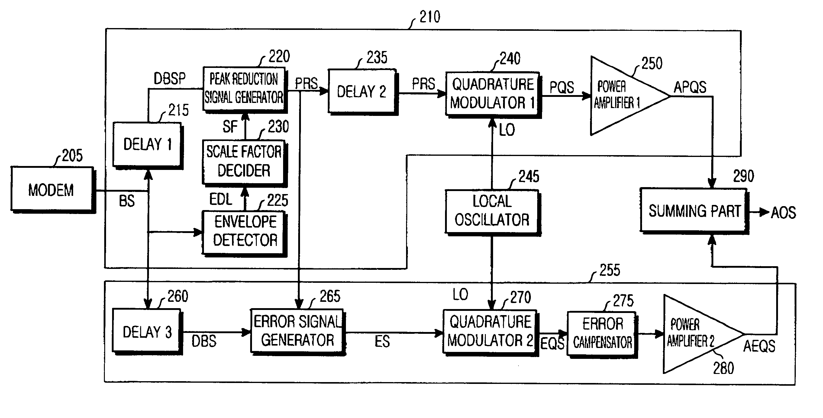
[0031]In accordance with the present invention, a peak signal is detected from a baseband signal with a large peak-to-average power ratio (PAR) by means of a power amplifier that amplifies a radio frequency (RF) signal. Individual power amplifiers amplify the detected peak signal and a resulting signal reduced by the peak signal, respectively, and then the amplified signals are combined. For these operations, components for detecting the peak signal and components for amplifying the peak signal will now be described.

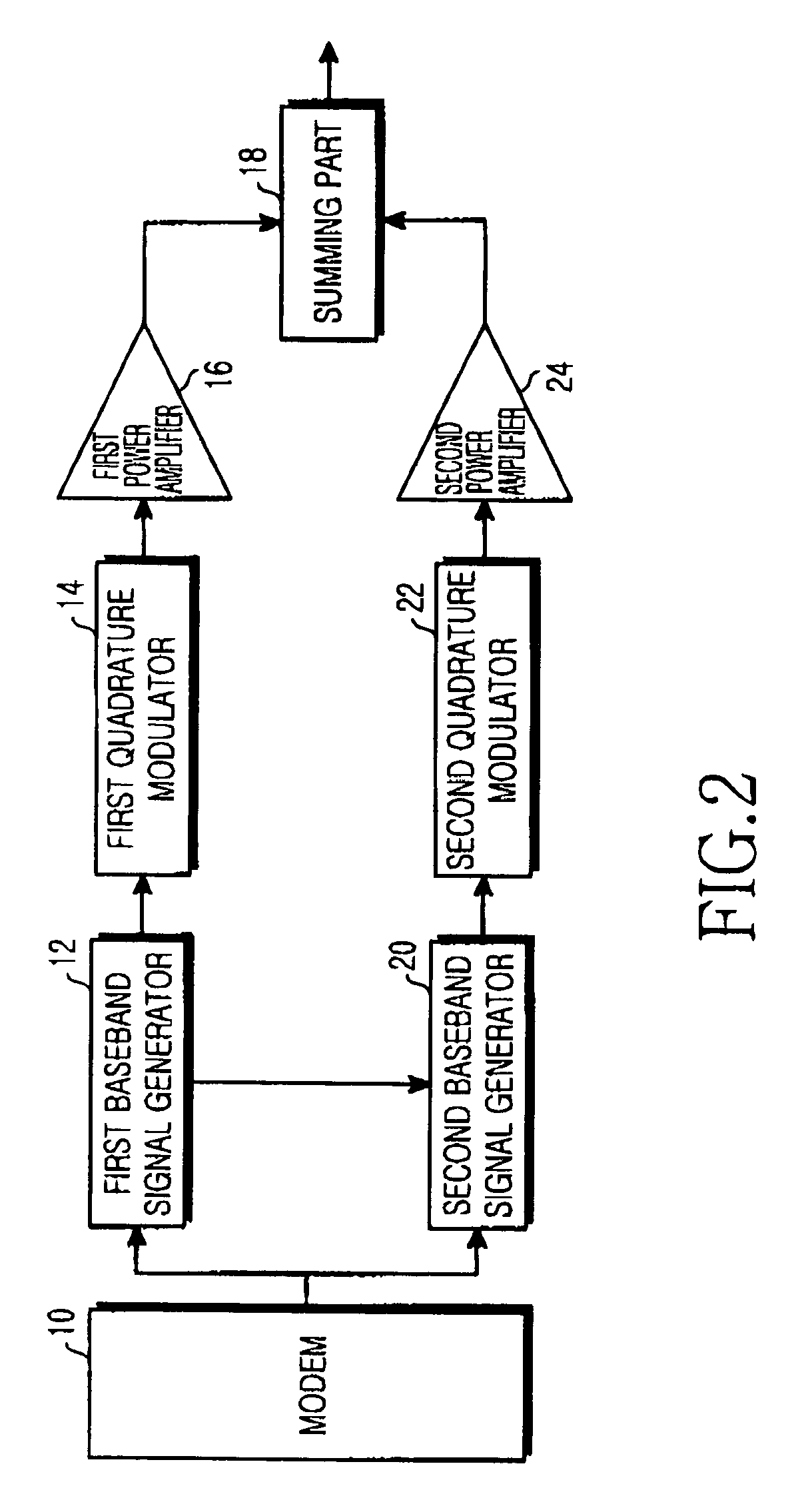
[0032]FIG. 2 is a schematic block diagram illustrating an apparatus for improving the efficiency of a power amplifier in accordance with one embodiment of the present invention. As shown in FIG. 2, the apparatus in accordance with the present invention comprises a modem 10, a first baseband signal generator 12, a second baseband signal generator 20...


PUM


Abstract

An apparatus and method for improving the efficiency of a power amplifier operating on the basis of a signal of a large peak-to-average power ratio (PAR). A main amplification part detects envelope values of an input baseband signal, reduces a peak value of the envelope values of the baseband signal to generate a peak reduced signal, amplifies the generated peak reduced signal, and outputs a first amplified signal. An error correction amplification part amplifies an error signal indicating a difference between the baseband signal and the peak reduced signal, and outputs a second amplified signal. A summing part combines the first amplified signal from the main amplification part and the second amplified signal from the error correction amplification part, such that high amplification efficiency is produced and an amplified output signal with reduced spectral regrowth in which an error is corrected can be outputted.

Description

PRIORITY[0001]This application claims priority to an application entitled “APPARATUS AND METHOD FOR IMPROVING EFFICIENCY OF POWER AMPLIFIER OPERATING UNDER LARGE PEAK-TO-AVERAGE POWER RATIO”, filed in the Korean Intellectual Property Office on Nov. 18, 2002 and assigned Serial No. 2002-71737, the contents of which are hereby incorporated herein by reference.BACKGROUND OF THE INVENTION[0002]1. Field of the Invention[0003]The present invention relates to a power amplifier, and more particularly to an apparatus and method for improving the efficiency of a power amplifier operating on the basis of a signal with a large peak-to-average power ratio (PAR).[0004]2. Description of the Related Art[0005]In conventional wireless communication systems such as cellular systems, a base station uses a power amplifier to communicate with user terminals distributed within a predetermined service area. The power amplifier amplifies a radio frequency (RF) signal for use in a communication system to tra...

Claims


Application Information

Patent Timeline
Patent Type & Authority Patents(United States)
IPC IPC(8): H04B1/02H03F1/02H03F1/32
CPCH03F1/02H03F1/0288H03F1/3229Y02B60/50
Inventor YOON, HYUN-SU
Owner SAMSUNG ELECTRONICS CO LTD
Features
  • Generate Ideas
  • Intellectual Property
  • Life Sciences
  • Materials
  • Tech Scout
  • Unparalleled Data Quality
  • Higher Quality Content
  • 60% Fewer Hallucinations
Learn More