High frequency interference-cut filter circuit

a filter circuit and high frequency technology, applied in the field of high frequency apparatus, can solve the problems of difficulty for apparatus b>100/b> to receive the originally desired signal, and achieve the effect of high reception quality

Active Publication Date: 2008-04-15
PANASONIC CORP
View PDF7 Cites 131 Cited by
  • Summary
  • Abstract
  • Description
  • Claims
  • Application Information

AI Technical Summary

Benefits of technology

[0010]A high frequency apparatus of the present invention comprises an interference-cut filter disposed between an input terminal and a mixer. This structure is intended to optimize a function of the interference-cut filter at least when there is transmission of interfering signals, and to avoid the problem of undesired interfering signals form causing an adverse effect to the normal transmission signals.
[0012]The interference-cut filter disposed between the input terminal and the mixer for removing the interfering signals is controlled in a manner that it operates when the interfering signals are transmitted. That is, the interference-cut filter is so controlled that it demonstrates the function while the interfering signals are transmitted. In other words, this invention has an advantage of excluding a drawback associated with insertion of the interference-cut filter and achieving high quality of reception, since it can cut off operation (or, function) of the interference-cut filter when there is no emission or output of interfering signals.

Problems solved by technology

Therefore, if the signal received in antenna 1 has a frequency adjacent to the frequency band of the desired wave being received, the communication signal (i.e., the transmission signal) output from cellular telephone 16 becomes an interfering signal, and this gives rise to a problem that it makes difficult for apparatus 100 to receive the originally desired signals.

Method used


Image

  • High frequency interference-cut filter circuit
  • High frequency interference-cut filter circuit
  • High frequency interference-cut filter circuit

Examples


first embodiment

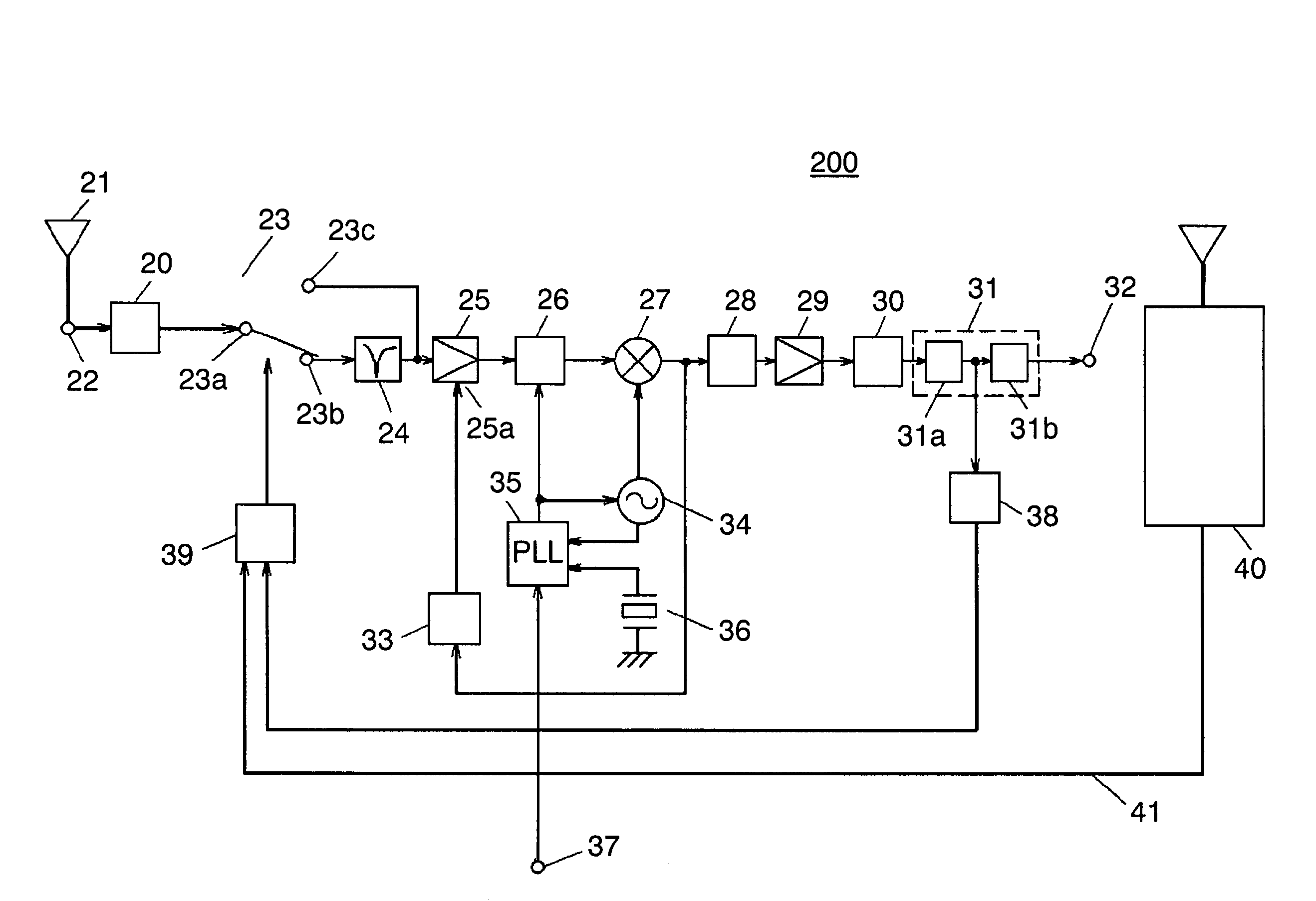
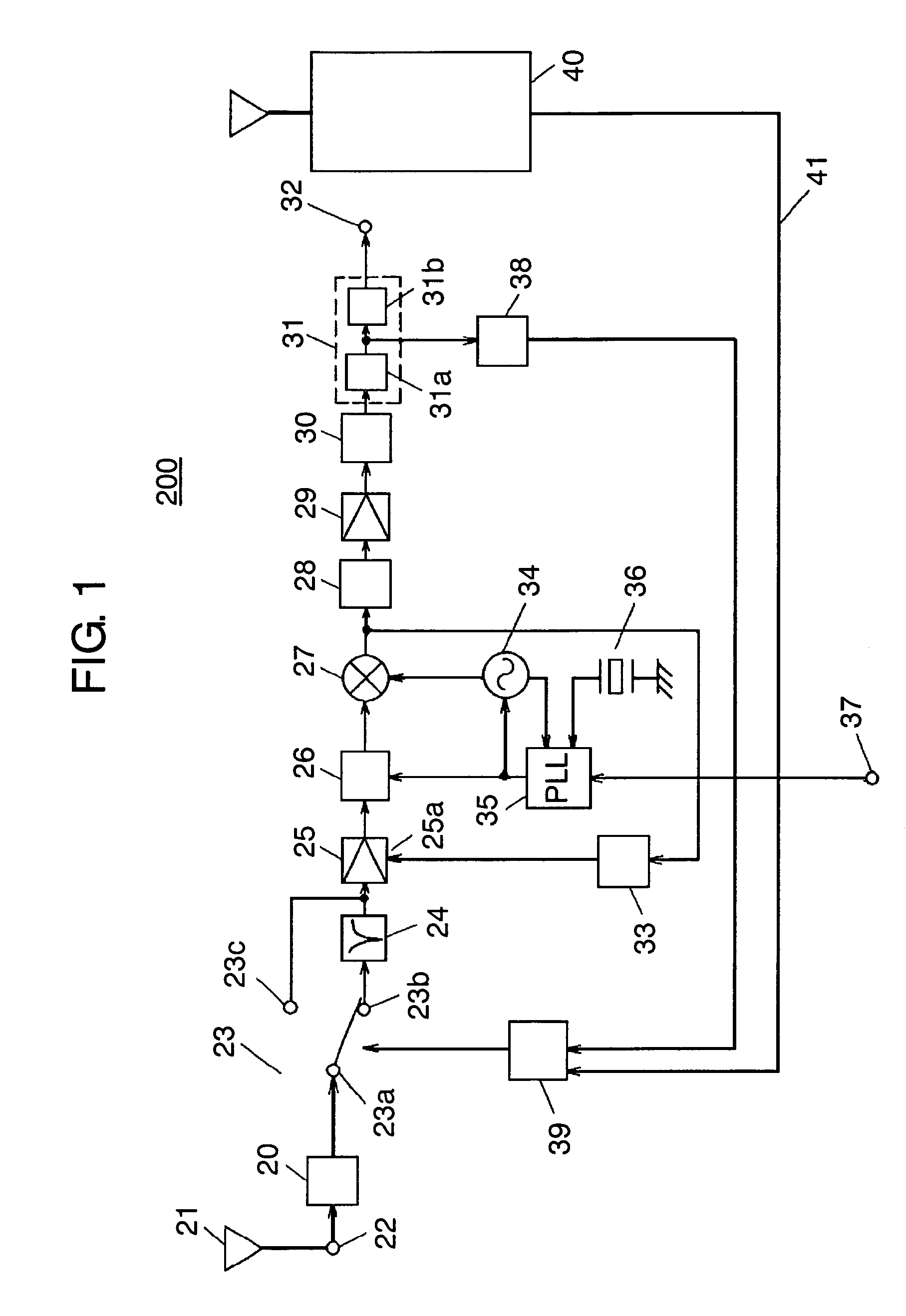
[0018]FIG. 1 is a block diagram of high frequency apparatus 200 according to the first embodiment of this invention. High frequency apparatus 200 of the first embodiment is suitable for removing interfering signals anticipated in advance as being exist in a given frequency band. This is based on a concept that the frequency band of undesirable signals output and transmitted by a cellular telephone is either known or foreseeable when, for instance, the cellular telephone is built in and mounted to high frequency apparatus 200.

[0019]In FIG. 1, high frequency apparatus 200 comprises input terminal 22 connected to antenna 21, and input filter 20 connected to input terminal 22. Apparatus 200 also comprises selector switch 23 having common terminal 23a in connection to an output of input filter 20, and interference-cut filter 24 connected to one side terminal 23b of selector switch 23 for the purpose of removing interfering signals. Apparatus 200 also comprises AGC amplifier 25 for receiv...

second embodiment

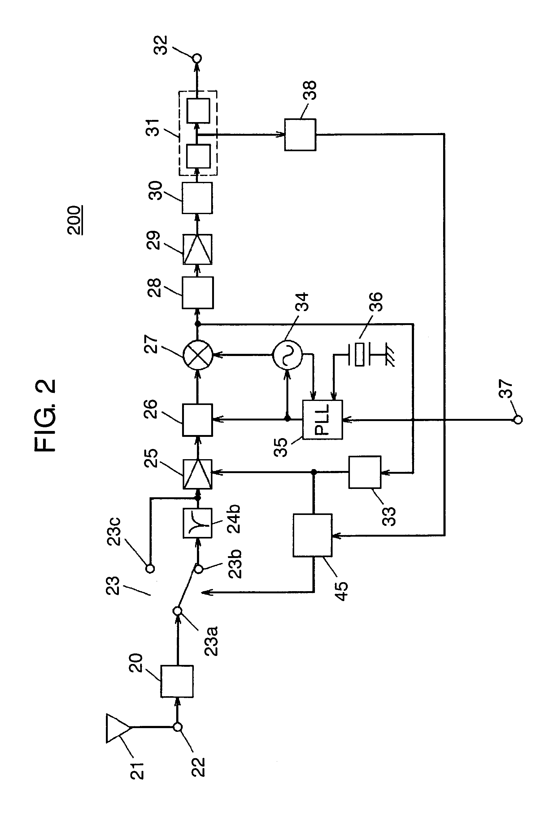
[0039]FIG. 2 is a block diagram of high frequency apparatus 200 according to the second embodiment of this invention. High frequency apparatus 200 described in this second embodiment is also intended to separate interfering signals of an anticipated frequency band, and to exclude them from the originally desired normal signals. One such example is the case in which analog broadcasting signals of 6 channel or 8 channel may exist as interfering signals when receiving digital broadcasting signals of the adjacent 7 channel.

[0040]In this instance, interference-cut filter 24b having a center frequency (any of 6 and 8 channels) is proved effective for the pre-determinate interference frequency (6 or 8 channels) input to antenna 21 from the outside.

[0041]The second embodiment is contrived to control selector switch 23 when there is a large input of interfering signals, and if the originally desired signals output from mixer 27 have a small amplitude. In the second embodiment, like reference...

third embodiment

[0045]FIG. 3 is a block diagram of high frequency apparatus 200 according to the third embodiment of this invention. High frequency apparatus 200 of this third embodiment is also proved effective when interfering signals exist in an anticipated frequency band. One such example is the case in which there is a manufactory and the like facility in the vicinity of a location where high frequency apparatus 200 of this invention is used, and emission of interfering signals is anticipated from there. Moreover, this embodiment is particularly effective when a frequency band of the interfering signals is known or foreseeable. Like reference marks are used to designate the like components as those of the first and second embodiments, and their descriptions will be abbreviated.

[0046]In FIG. 3, interference-pass filter 46a for passing interference frequency is connected to input terminal 22, and interfering signal detector 47 is connected between an output of interference-pass filter 46a and a ...


PUM


Abstract

Disclosed is a high frequency apparatus which eliminates an influence of interfering signals. An interference-cut filter (24) for eliminating interfering signals is disposed between an input terminal (22) and a mixer (27). The interference-cut filter (24) is so controlled that it effectively demonstrates the function while the interfering signals are transmitted. Control of the interference-cut filter (24) is made by a switch (23), which is controlled by a selector switch controller (39), and the switch controller (39) is controlled responsive to an error correction counter (38) and a radio wave transmitted from a cellular telephone (40). This structure eliminates interference attributable to communication signals transmitted by the cellular telephone (40) and undesirable signals entering from the outside. The invention can thus realize high quality reception.

Description

TECHNICAL FIELD[0001]The present invention relates to a high frequency apparatus used for receiving ground waves and satellite waves of digital and analog broadcasting. More specifically, the invention relates to the high frequency apparatus capable of suppressing and eliminating adverse influences of interfering signals attributable to other broadcasting signals in frequencies adjacent to the original frequency band of which reception is sought.BACKGROUND ART[0002]FIG. 4 shows an example of a high frequency apparatus of the prior art. That is, the conventional high frequency apparatus 100 comprises input terminal 2 in connection to antenna 1, and input filter 3 connected to input terminal 2. Apparatus 100 also comprises AGC amplifier 4 connected to an output of input filter 3 and provided with an AGC control terminal, tuning filter 5 connected to an output of AGC amplifier 4, mixer 6 having one of input ports connected with an output of tuning filter 5, and intermediate frequency f...

Claims


Application Information

Patent Timeline
Patent Type & Authority Patents(United States)
IPC IPC(8): H04B1/06H03J3/20H04B1/00H04B1/10H04B15/00H04B15/02
CPCH04B1/1036H04B1/109H04B1/525H04N5/21
Inventor ADACHI, KENJIUMEDA, TAKASHI
Owner PANASONIC CORP
Why Eureka
Try Eureka