Articulating bail assembly and method

a technology of articulating bails and bails, which is applied in the direction of sealing/packing, drilling pipes, and wellbore/well accessories, etc., can solve the problems of affecting the work efficiency of drillers, and affecting the operation of drillers, etc., and achieves the effect of convenient tool handling

Active Publication Date: 2008-04-22
DEVIN INT
View PDF4 Cites 21 Cited by
  • Summary
  • Abstract
  • Description
  • Claims
  • Application Information

AI Technical Summary

Benefits of technology

[0011]An advantage of the present invention is that the assembly forms a work window. Another advantage is that the assembly can be used with wireline, coiled tubing, or snubbing strings. Yet another advantage is that the assembly forms a vertical frame in the derrick, but can also be laid horizontally on the deck. Still yet another advantage is that the assembly can more easily handle tools during rig-up and rig-down than prior art tools due to the dual articulation from the top pivot point and the lower pivot point.
[0012]A feature of the present invention is the door in lower spreader. The door can be hydraulically or pneumatically operated for opening and closing, and wherein when the door is opened tubular members can be placed therein, and when closed, the door will capture the tubular therein. Another feature is that the door can be automatically controlled from a distance. Still yet another feature is that when the door is closed, the weight of the equipment can be transferred to the second spreader member and in turn to the assembly. Another feature is that the spreader member can act as an elevator for lifting and lowering tubulars and equipment.
[0013]Still yet another feature is that the bails in the most preferred can be an I-beam iron segment. Yet another feature is that the bails can be simply shortened or lengthened which in turn allows for either a shorter work window or a longer work window. Another feature is that most parts are interchangeable, and therefore, it is possible to assemble various size assemblies without having to manufacture all the various parts.

Problems solved by technology

In deep water, a fixed leg type platform is generally not an option due to the extreme water depths.
In the deep water drilling of subterranean reservoirs, drillers encounter numerous operational problems.
Also, tidal conditions may cause a variation in platform height and cause similar buoyant forces.
Normal derrick space may be inadequate, and therefore, operators have used a lift frame in order to aid in rigging-up this type of equipment.
However, prior art lift frames suffer from several problems including extreme difficulty in maneuvering and rigging-up equipment.
In other words, the prior art designs of lift frames make it very difficult to rig-up and rig-down equipment.

Method used


Image

  • Articulating bail assembly and method
  • Articulating bail assembly and method
  • Articulating bail assembly and method

Examples


Embodiment Construction

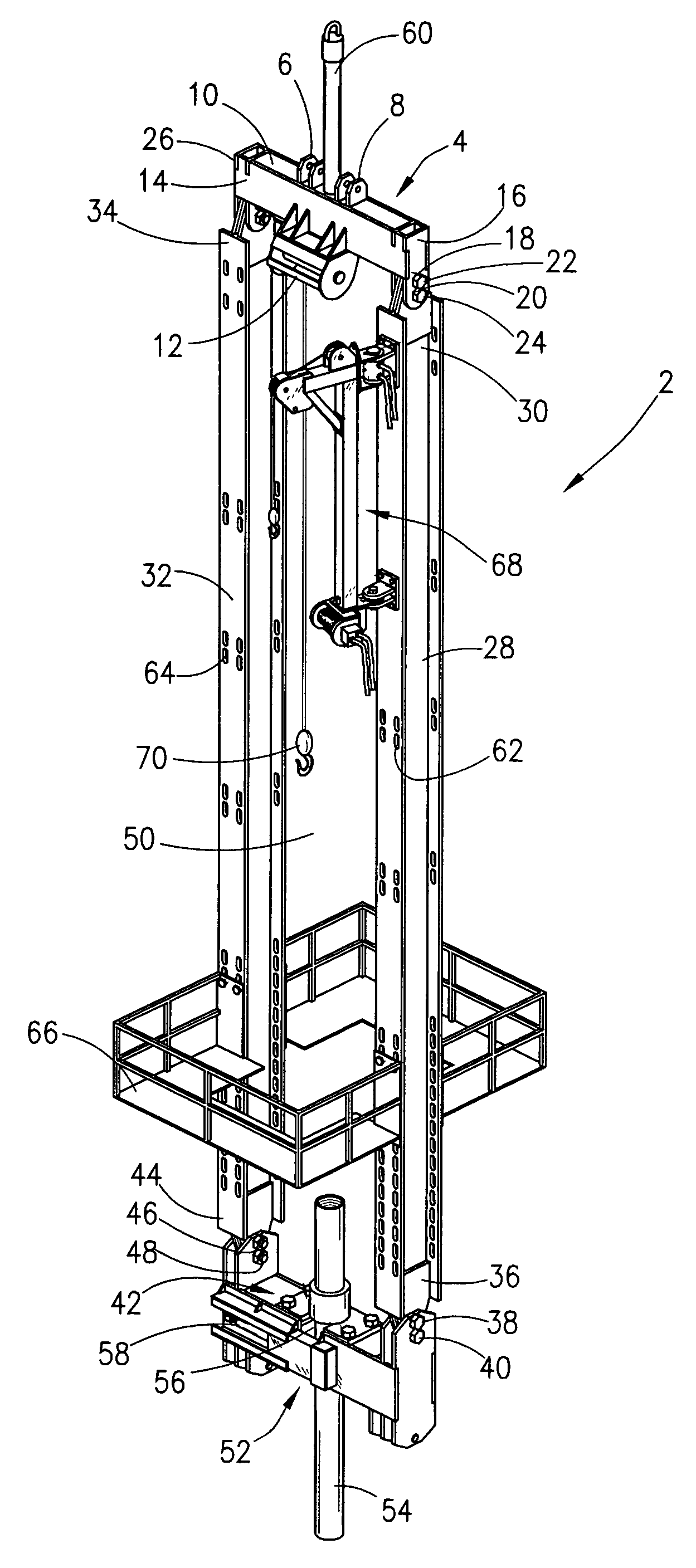
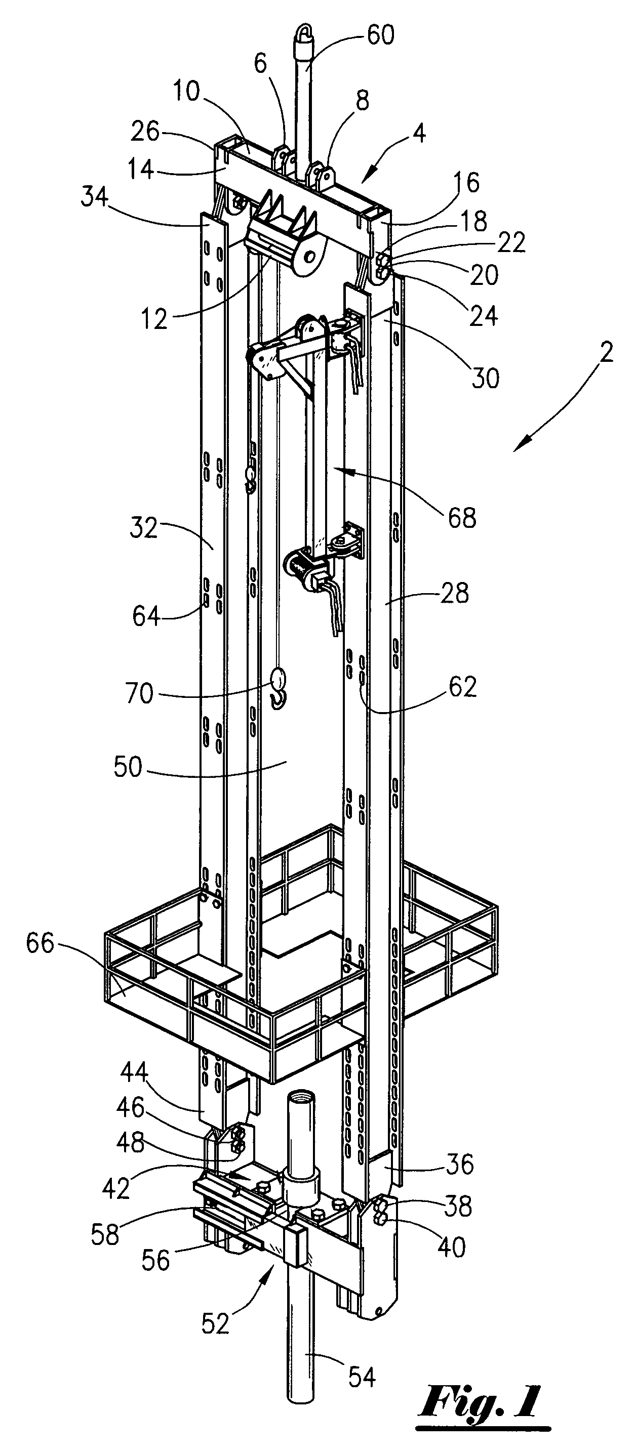
[0021]Referring now to FIG. 1, a perspective view of the most preferred embodiment of the articulating bail assembly 2 will now be described. The assembly 2 includes a spreader member 4 (sometimes referred to as the upper spreader member) that is generally a rectangular box structure, and wherein the spreader member 4 contains a first pad-eye means 6 and second pad-eye means 8 disposed through the top side 10 and attached to the spreader 4. Additionally, the spreader member 4 will have a winch means 12 for winch objects, and wherein the winch means is attached to the side 14. Also, the spreader member 4 has another side 16, and wherein side 16 contains the apertures 18, 20 that will have disposed therein pins 22, 24. The pins 22, 24 will server as pins for pivoting as will be more fully explained later in the application. On an opposite side of 16 is side 26, and wherein side 26 will have a pair of apertures that contains a pair of pins (not seen in this view).

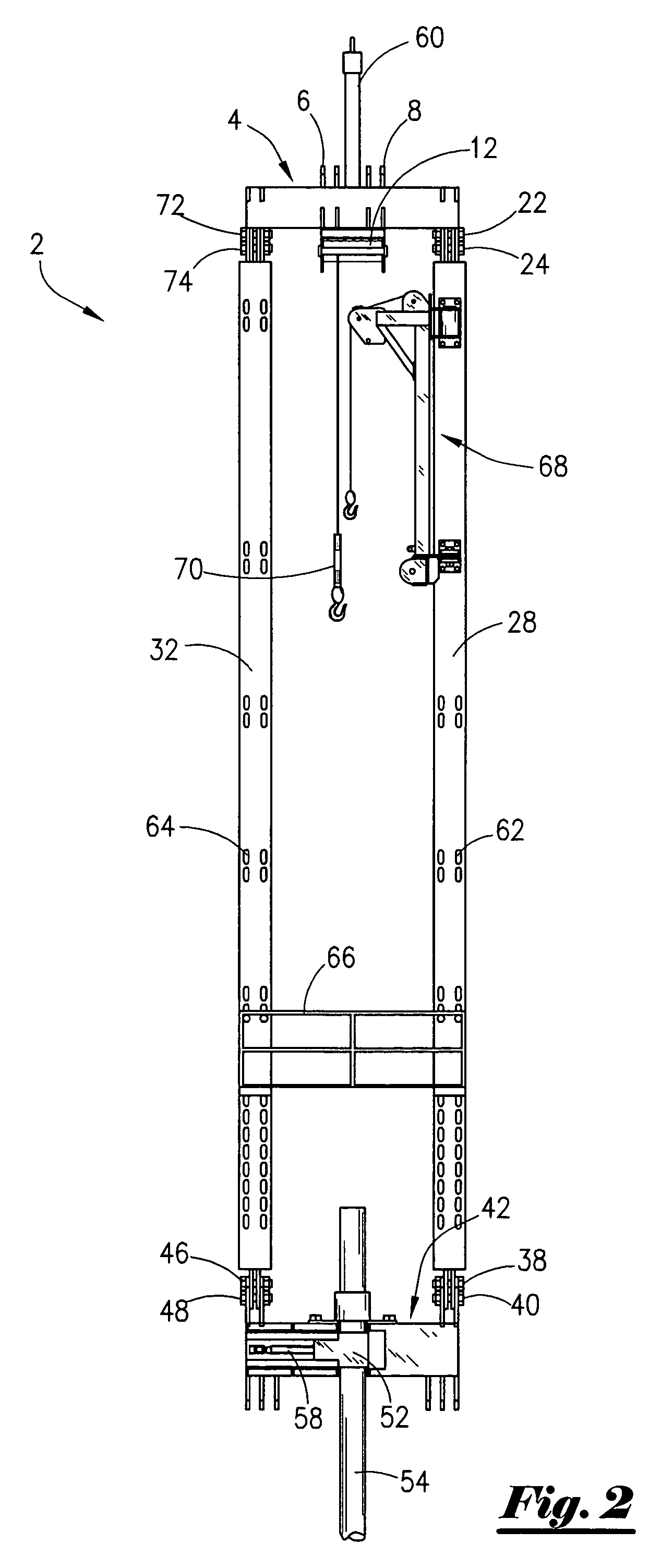
[0022]As seen in FIG. ...


PUM

PropertyMeasurementUnit
depthsaaaaaaaaaa
depthsaaaaaaaaaa
weightaaaaaaaaaa

Abstract

An apparatus for performing well intervention work on a rig. The apparatus comprises a first spreader that is operatively connected to a derrick, a pair of I-beams that have a distal end and a proximal end, and wherein the distal end of the pair of I-beams are connected to the first spreader. The apparatus further comprises a second spreader, and wherein the proximal end of the I-beams is connected to the second spreader. The apparatus further comprises a first pivot point on the first spreader and a second pivot point on the second spreader. In the most preferred embodiment, the apparatus further comprises a door, operatively attached to the second spreader, for allowing entry of the tubular. Also, the second spreader may include a shoulder for engagement with a tubular so that the tubular is supported by the second spreader so that the weight of the tubular can be transferred to the second spreader. A method of lifting a tubular used in well intervention work on a rig is also disclosed.

Description

[0001]This invention relates to an apparatus used for well intervention work. More specifically, but not by way of limitation, this invention relates to an articulating bail assembly and method used on offshore platforms operatively associated with subterranean wells.[0002]The search for hydrocarbons has led operators to explore and drill in remote and exotic areas of the globe. Deep water tracts have been explored and drilled with increasing frequency in recent years. Platforms set in waters of 1,000 to 2,000 feet has become common place, and in some instances, wells have been drilled in water depths of 5,000 feet. Different types of drilling and production platforms have been used in these deep waters. One type of platform is a tension leg platform (TLP). In the TLP, a floating platform is connected to the ocean floor via tendons such as steel cables, as is well understood by those of ordinary skill in the art. Another type of structure used in deep water is the spar platform whic...

Claims


Application Information

Patent Timeline
Patent Type & Authority Patents(United States)
IPC IPC(8): E21B19/18
CPCE21B19/06E21B19/02E21B33/02
Inventor MONCUS, JAMES DEVINMILLER, JR., JOSEPH HAYDENDUHON, BRYAN
Owner DEVIN INT
Why Eureka
Try Eureka