Sense optimized MRI RF coil designed with a target field method

a target field and sensing coil technology, applied in the field of sensing optimized mri rf sense coils, can solve the problems of limited scope, unfavorable optimum, and uneven spatial distribution of signal to noise ratios in images,

Active Publication Date: 2008-04-22
RGT UNIV OF CALIFORNIA
View PDF7 Cites 15 Cited by
  • Summary
  • Abstract
  • Description
  • Claims
  • Application Information

AI Technical Summary

Benefits of technology

[0018]The method of the illustrated embodiment solves the inverse problem from that described above in the prior art, where the best coil topography is calculated based on the performance criteria specified by the designer. Prior art uses basic coil geometries, such as circular or rectangular forms, whereas the coil structure of the illustrated embodiment can assume any arbitrary shape to get the best performance. The coil design criteria of the illustrated embodiment begins with finding the current distribution on a prescribed or predetermined three or two dimensional surface that will maximize the signal-to-noise within the volume of interest. Therefore, the outcome will be the highest possible SNR among all possible coil designs.
[0023]Thus, the illustrated embodiment solves the inverse problem of calculating the probe coil topography, given the target volume and acceleration factor. The SNR in a SENSE-MR image, SNRsense, is inversely proportional to the g-factor. One can formulate the g-factor in terms of the magnetic field distribution or sensitivity profiles of the coils. Then, by specifying the geometry of the desired coil former and using finite element mesh (FEM), it is possible to find the surface current distribution to maximize SNRsense, in the target volume.

Problems solved by technology

However, this will cause aliasing in the resulting image.
Due to non-uniform B1 (RF) field distributions with these coil arrays, the spatial distribution of the signal to noise ratio (SNR) in the images is not uniform.
This approach is restricted by the limited number of coils simulated, and the result will most likely not be the most optimum.
Although this approach may yield a better design compared to other prior approaches, it still has limited scope because the basic design shape still conforms to rectangular geometry and the size of each coil loop is changed to optimize the design.
In the past, MRI designers have used general-purpose MRI RF coil structures, which were not optimized for accelerated SENSE imaging technique.
The geometry factor is a mathematical function of the coil sensitivities and the reduction factor R. However, its structure does not permit straightforward analytical coil optimization, making simulations an indispensable tool in seeking optimized coil arrangements for sensitivity encoding.
Therefore, the signal-to-noise ratio (SNR) was not maximized for SENSitivity Encoding technique (SENSE).
But none of the designs that were tested had been designed to minimize the geometry factor g of parallel imaging technique to maximize the signal-to-noise ratio.
Therefore, this approach does not guarantee the best possible performance among all possible coil designs.

Method used


Image

  • Sense optimized MRI RF coil designed with a target field method
  • Sense optimized MRI RF coil designed with a target field method
  • Sense optimized MRI RF coil designed with a target field method

Examples


Embodiment Construction

[0036]In the illustrated embodiment, a method for designing MRI RF coil arrays 10 is disclosed that maximizes the SNRsense within a target volume using a target field approach. This method is based on solving the inverse problem of finding a surface current density distribution on a defined coil former 12 using a least squares approach that minimizes 1 / SNRsense. If gρ is minimized within the volume of interest by the appropriate coil design, SENSE imaging artifacts will be reduced and SNR will be maximized within that volume.

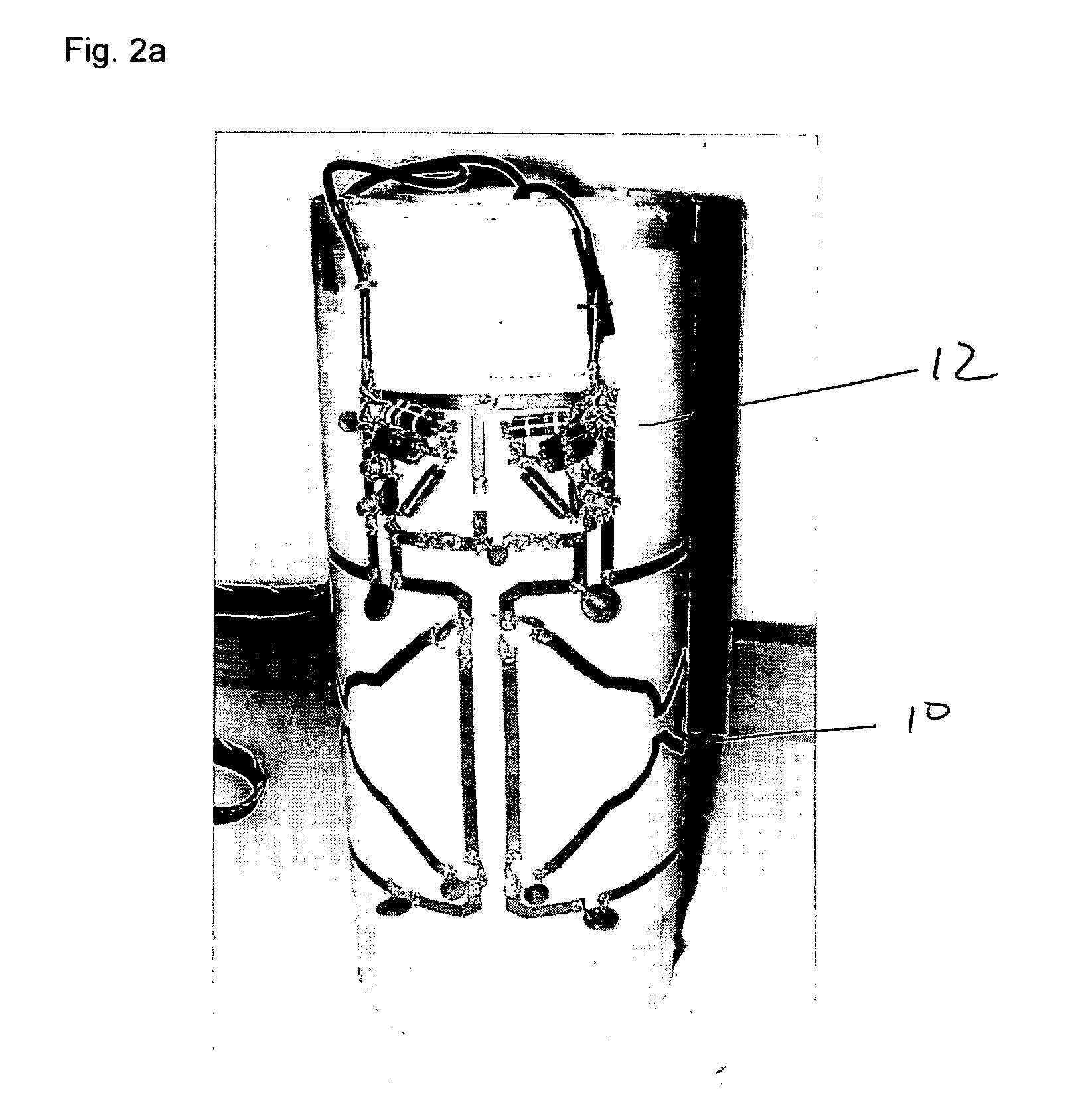
[0037]A coil array 10 is comprised of wires placed on a predefined surface 12 in three dimensional space, which can be approximated by a surface current density Js: It must be understood that the invention expressly contemplates that the predefined surface 12 can be any simple, complex, analytic or nonanalytic shape, but a cylindrical surface 12 was chosen for the illustrated embodiment of FIG. 2a for ease of example. The surface on which Js flows can be approxi...


PUM

PropertyMeasurementUnit
diameteraaaaaaaaaa
diameteraaaaaaaaaa
diameteraaaaaaaaaa

Abstract

An MRI RF coil that is optimized for SENSE imaging is used in a method where the surface current density distribution on a coil former was calculated to maximize the SNRsense within a volume of interest. An analytic relationship was formulated between the SNRsense and surface current density on the coil former. The SNR at pixel ρ in a SENSE-MR image, SNRsense,ρ, is inversely proportional to the g-factor. The g-factor was formulated in terms of the B1 distribution of the coils. By specifying the geometry of the desired coil former and using a finite element mesh, the surface current distribution was calculated to maximize the SNRsense, by minimizing (1 / SNRsense) in the volume of interest using a least squares procedure. A simple two-coil array was tested and phantom images were collected. The results show that the new coil design method yielded better uniformity and SNR compared to standard coils.

Description

RELATED APPLICATIONS[0001]The present application is related to U.S. Provisional Patent Application, Ser. No. 60 / 675,356, filed on Apr. 27, 2005, which is incorporated herein by reference and to which priority is claimed pursuant to 35 USC 119.BACKGROUND OF THE INVENTION[0002]1. Field of the Invention[0003]The invention relates to the field of magnetic resonance imaging (MRI) and in particular to optimization of MRI RF sense coil designs for the best signal to noise ratios given a volume of interest and a surface shape on which the coil is to be formed.[0004]2. Description of the Prior Art[0005]Parallel imaging methods have been recently introduced in MRI that allows faster data acquisition using distinct information coming from an array of RF coils. One of these techniques is known as SMASH (Simultaneous Acquisition of Spatial Harmonics). In SMASH a sparsely sampled k-space is collected in the phase encode direction, thus reducing the total image collection time. However, this will...

Claims


Application Information

Patent Timeline
Patent Type & Authority Patents(United States)
IPC IPC(8): G01V3/00B23P17/04H01F7/06
CPCG01R33/3415G01R33/34007Y10T29/49018Y10T29/4902Y10T29/49071Y10T29/49
Inventor MUFTULER, LUTFICHEN, GANGNALCIOGLU, ORHAN
Owner RGT UNIV OF CALIFORNIA
Why Eureka
Try Eureka