Probe with contact ring

a technology of contact rings and probes, which is applied in the field of spring probes, can solve the problems of poor, unreliable electrical performance of probes, poor etc., and achieve the effect of improving the pointing accuracy of probes

Active Publication Date: 2008-04-22
SMITHS INTERCONNECT AMERICAS INC
View PDF9 Cites 14 Cited by
  • Summary
  • Abstract
  • Description
  • Claims
  • Application Information

AI Technical Summary

Benefits of technology

[0007]The present invention provides a probe with a barrel, spring and plunger biased outwardly from the barrel by the spring. The probe includes one or more contact rings in electrical contact with the tail of the plunger to ensure electrical contact between the plunger and the barrel. The contact ring provides a consistent electrical contact throughout the travel of the plunger within the barrel and improves the pointing accuracy of the probe.

Problems solved by technology

The resultant probe often performs well mechanically but the electrical performance in certain instances is compromised by the action of the spring and device under test.
The result is a poor, unreliable electrical performance for the probe.
A common spring, by nature of its design and composition, has a very large resistance and causes poor-electrical performance of the probe if it is the main circuit path.
Likewise, large resistances between the barrel inner diameter (“ID”) and plunger, referred to as the internal contact resistance, may also lead to poor electrical performance or failure of the probe.
Large internal contact resistances are generally due to low contact force between barrel ID and plunger, poor conductive material of barrel and plunger including plating material and contaminates such as dirt, lint, or lubricants.
The disadvantage to this type of design is the higher friction that is created between plunger and barrel resulting in failure of the probe due to mechanical wear.
Another problem is often the pointing accuracy of the probe suffers with a bias cut design.
Additionally, as the probe wears, the pointing accuracy may degrade.

Method used


Image

  • Probe with contact ring
  • Probe with contact ring
  • Probe with contact ring

Examples


Embodiment Construction

[0019]Detailed embodiments of the invention are disclosed herein, however, it is to be understood that the disclosed embodiments are merely exemplary of the invention which may be embodied in various forms. Therefore, specific structural and functional details disclosed herein are not to be interpreted as limiting, but rather merely as a basis for teaching one skilled in the art to variously employ the present invention in any appropriately detailed form, and as a basis for the claims.

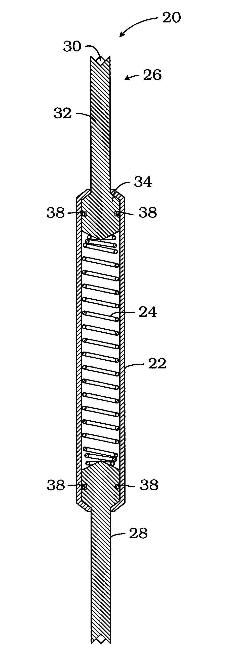
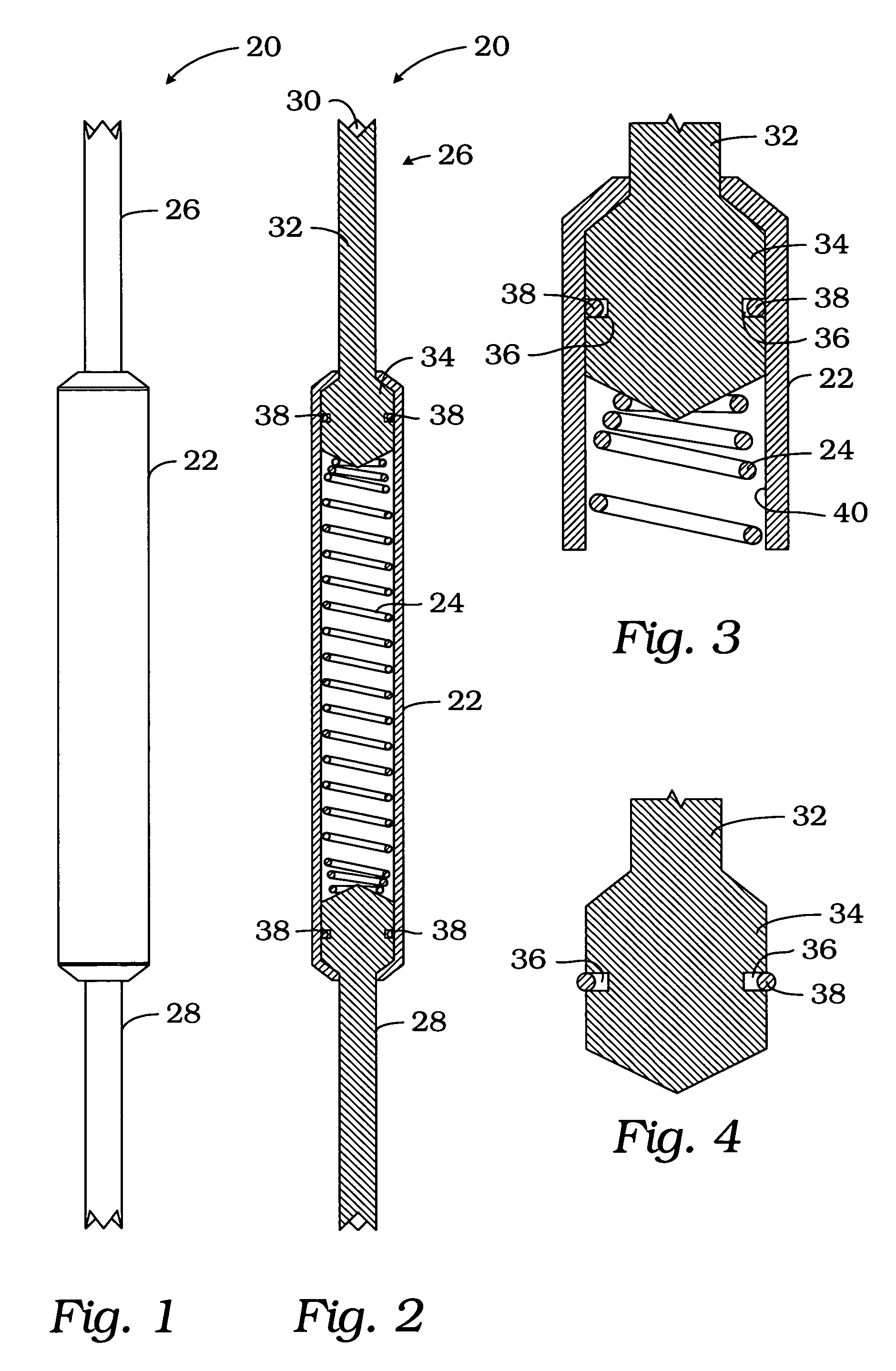
[0020]Referring to FIGS. 1-4, a test probe of the present invention is generally indicated by reference numeral 20. Probe 20 includes an elongated tubular barrel 22, a spring 24 seated within the barrel 22, and a pair of plungers 26 and 28 slideably mounted within the barrel and extending outwardly therefrom for contacting a test point of a device under test. It should be understood that the drawings of a double-ended probe is for illustrative purposes only. The teachings herein may be applied to other...


PUM


Abstract

A spring probe having a barrel, plunger, spring and contact ring is provided in which the contact ring provides electrical contact between the plunger and the barrel. Two or more contact rings may be provided to improve the pointing accuracy of the probe.

Description

FIELD OF THE INVENTION[0001]The present invention relates to spring probes and, more particularly, to spring probes with improved electrical performance and pointing accuracy.BACKGROUND OF THE INVENTION[0002]Conventional spring-loaded electrical contact probes generally include an outer receptacle, a barrel containing a movable plunger and a spring, which exerts a force against the tail of the plunger to bias the plunger outwardly from the barrel. The plunger may be depressed inwardly into the barrel a predetermined distance, under force directed against the spring.[0003]Battery-type contacts and interconnect probes generally require compact, durable, highly reliable designs with circuit paths optimized for the best performance. These contacts and probes are typically employed in battery charging applications, mobile telecommunication applications, docking applications, and other portable electronic devices in addition to applications for testing electronics, printed circuit boards ...

Claims


Application Information

Patent Timeline
Patent Type & Authority Patents(United States)
IPC IPC(8): G01R31/02
CPCG01R1/06722
Inventor HENRY, DAVID W.THURSTON, WILLIAM E.
Owner SMITHS INTERCONNECT AMERICAS INC
Why Eureka
Try Eureka