
Hand pressure sensor warning device

a hand pressure sensor and warning device technology, applied in the direction of sensors, diagnostics, sports equipment, etc., can solve the problem of unintended loosening of the warning device from a handheld object during its use,

Inactive Publication Date: 2008-04-22
BOS ARIE CORNELIS
View PDF19 Cites 11 Cited by
  • Summary
  • Abstract
  • Description
  • Claims
  • Application Information

AI Technical Summary

Benefits of technology

[0017]This new hand pressure sensor warning device is designed as a relatively thin band-aid or sticking plaster to attach the warning device onto the outside surface of the handgrips of handheld devices, making the attachment to and detachment from the handheld device very simple and user-friendly. Secondly, the minimal dimensions and mass of the new device have a negligible influence on the appropriate moment of inertia of the hand held device. The unintended coming loose of the warning device from a handheld object during its use is not possible while the hand or finger presses the warning device against the object. Due to its low manufacturing costs, the warning device is also highly attractive as a commercial advertising product and as a corporate gift or premium product.
[0021]The attachment of the warning device to the sport etc. device is preferably done by means of the double sided, adhesive tape, thereby eliminating the use of a band-system with “C” clips or the use of velcron tape. Unwanted coming loose of the warning device from the sports etc. device is very unlikely because the warning device is fully covered at least one hand during it use.
[0027]Another important aspect of the invention is that the first and the second membrane layers of the membrane switch are mutually positioned and fixed at a distance by means of a perforated isolating layer between the two membrane layers. This perforated isolating layer can be a glue layer with regular openings, whereby the openings correspond to the contact areas of at least one membrane layer. In this way a simple, accurate hand pressure switch can be constructed, which can easily be adapted to its desired application by varying the contact areas and / or the perforated glue layer leading to a in this way adjustable threshold hand pressure value of the membrane switch to close. The isolating layer can have a constant thickness, but the thickness can also change e.g. linear over the length of the membrane layer when a difference in pressure sensitivity dependent of the position on the surface of the membrane switch is needed.
[0035]To increase the flexibility of the membrane switch the second membrane layer can comprise cuts or grooves extending lengthwise thereby facilitating bending widthwise of the membrane switch perpendicular to its longitudinal axis for easy fit on a sport etc. device with a circular cross-section.
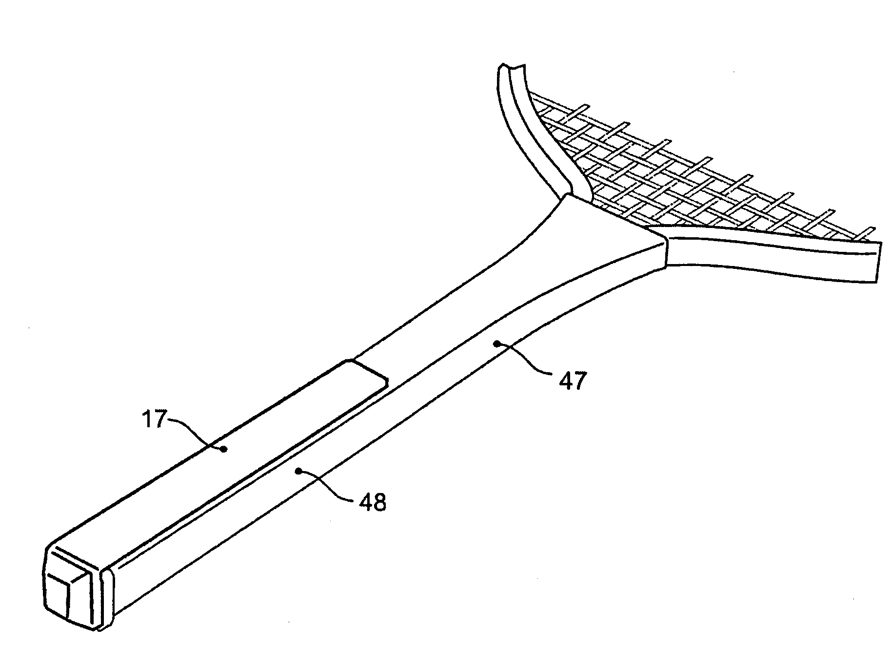
[0036]Preferably the domes formed in the second membrane layer are provided with cuts for lowering the hand or finger threshold value of the membrane switch. Preferably the electrical indicator is attached to the first membrane layer and connected to the contact areas of the first membrane layer, whereby the integrated alarm device is attached to the electrical indicator and where on top of the second membrane layer the housing element is attached covering the membrane layers of the membrane switch and covering in a bulge the electrical indicator with attached integrated alarm device. The hand pressure warning device can in this way be constructed at low cost and with dimensions which will fit most handgrips of sport etc. devices.
[0037]All individual components of the device can be mass-manufactured, as well as their assembly, allowing low final product lost. This makes it possible to use the device as a commercial advertising product, corporate gift or premium product.

Problems solved by technology

Secondly, the minimal dimensions and mass of the new device have a negligible influence on the appropriate moment of inertia of the hand held device.
The unintended coming loose of the warning device from a handheld object during its use is not possible while the hand or finger presses the warning device against the object.

Method used


Image

  • Hand pressure sensor warning device
  • Hand pressure sensor warning device
  • Hand pressure sensor warning device

Examples


Embodiment Construction

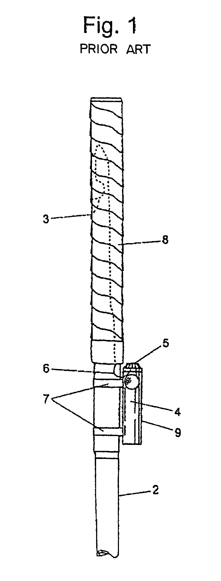
[0066]FIG. 1 shows the well known device for golf club handgrip training 1 according to U.S. Pat. No. 5,374,541. It contains a pressure sensor 3, which uses a spirally shaped band 8, fixed to the handgrip area of golf club 2. Pressure sensor 3 is connected by means of an electrical wire 6 with electrical indicator 4. Electrical indicator 4 is, together with connected alarm device 5 contained into the cylindrical housing element 9, which is fixed to the golf club 2 by means of “C” clips.

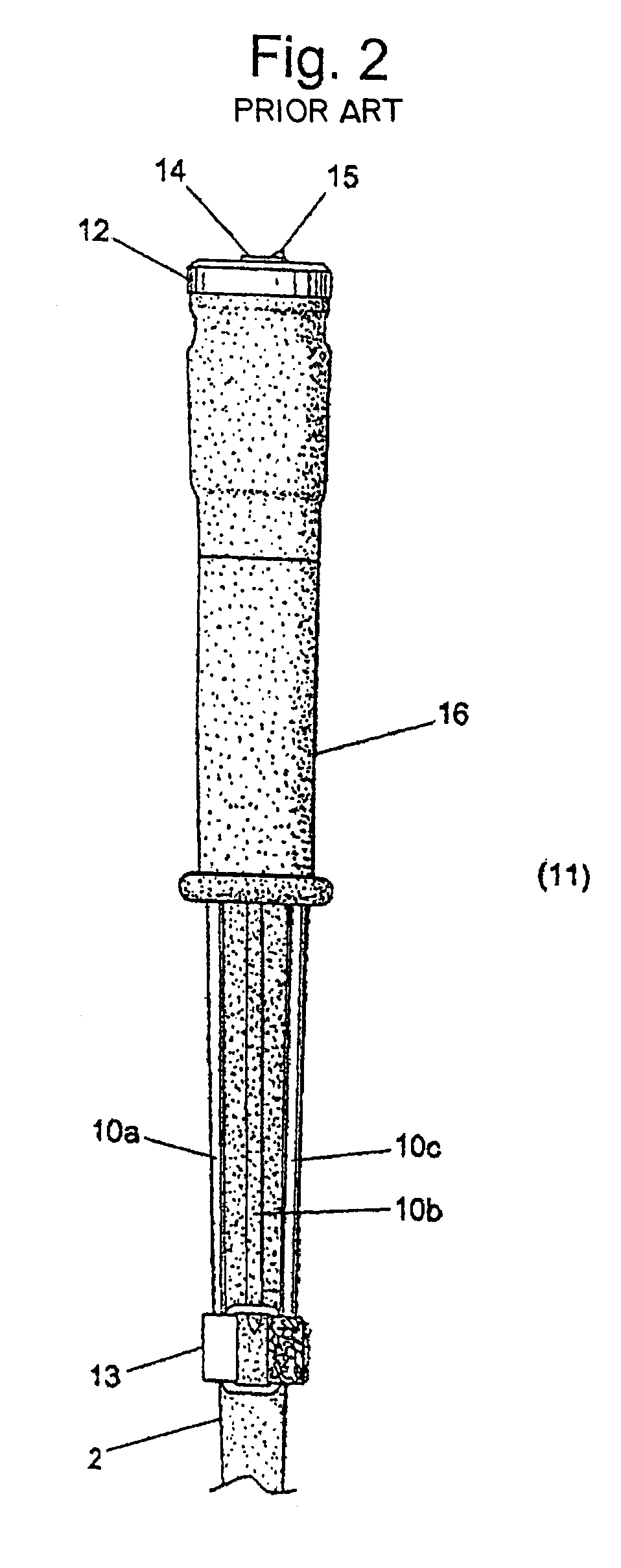
[0067]FIG. 2 shows the well known device for golf club handgrip training 11 according to WO 95 / 311258, which consists of oblong pressure sensor strips 10a, 10b and 10c, having pressure sensor elements (not shown), being positioned on golf club 2 by means of holder 12, and under-collar 13. The indicator (not shown) as well as the electronics (not shown) also are located in holder 12, and alarm device 14 and on / off switch 15 are located on its topside. Device 11 is fixed to golf club 2 by means of a cyl...


PUM

PropertyMeasurementUnit
diameteraaaaaaaaaa
thresholdaaaaaaaaaa
pressureaaaaaaaaaa

Abstract

An ergonomic lightweight hand pressure sensor-warning device for use with hand held objects like sport devices, steering devices, writing devices or computer devices, as well as the method for its assembly. This new hand pressure sensor warning device is designed as a relatively thin plaster / band-aid to attach the device onto the outside surface of the handgrips of hand held devices like a golf club, making the attachment to and detachment from the hand held device very simple and user-friendly. The device contains an electrical membrane switch, an electrical indicator with an alarm device and a streamlined oblong housing element which contains the principal components in a compact unit. Due to its low manufacturing costs, the warning device is also highly attractive as a commercial advertising product and as a corporate gift or premium product. The unintended and unexpected detachment of the device during a golf swing is practically impossible.

Description

CROSS REFERENCES TO RELATED APPLICATIONS[0001]This patent application claims priority from Netherlands Application No. 1021045 filed Jul. 10, 2002, Netherlands Application No. 1022654 filed Feb. 12, 2003, and PCT Application No. EP20 / 03007481 filed Jul. 10, 2003.BACKGROUND OF THE INVENTION[0002]1. Field of the Invention[0003]The invention relates to an ergonomic lightweight hand pressure sensor-warning device, for use with handheld objects like sport devices, steering devices, writing devices or computer devices, as well as the method for its assembly.[0004]The invention also relates to an assembly method of a hand pressure sensor warning device. The invention also relates to a membrane switch for use in a hand pressure sensor warning device.[0005]2. Background Art[0006]The warning device is used to correct handgrip forces applied to handgrips of handheld objects or equipment, in particular for use with sports devices including but not limited to tennis, squash, badminton, table ten...

Claims


Application Information

Patent Timeline
Patent Type & Authority Patents(United States)
IPC IPC(8): G08B21/00A61B5/22A63B21/02A63B57/00A63B69/36G01L1/20A63B59/00A63B71/06G01L5/00G01L5/22H01H3/14H01H9/06H01H13/08
CPCA63B71/06G01L5/22H01H3/142H01H2231/01A63B2071/0625A63B2071/0627A63B2071/0655A63B2071/0658A63B2220/56A63B2220/833A63B2225/30A63B2243/0004A63B2243/0016A63B2243/0029A63B2243/0041A63B2243/0083A63B2243/0091H01H9/06A63B2059/0022A63B2102/32A63B2060/464A63B2102/20A63B2102/16A63B2102/02A63B2102/22A63B2102/18A63B53/14A63B49/08A63B59/50A63B60/46
Inventor BOS, ARIE CORNELIS
Owner BOS ARIE CORNELIS
Learn More