Heat spreader with filtering function and electrical apparatus

a technology of heat spreader and filter function, which is applied in the direction of electric apparatus casings/cabinets/drawers, instruments, liquid fuel engines, etc., can solve the problems of affecting the operation stability of electronic elements, affecting the temperature of electronic elements continuously rising, and generating a large amount of heat, so as to save time and money for users

Active Publication Date: 2008-04-22
ASUSTEK COMPUTER INC
View PDF6 Cites 30 Cited by
  • Summary
  • Abstract
  • Description
  • Claims
  • Application Information

AI Technical Summary

Benefits of technology

[0010]In view of the foregoing, the invention is to provide a heat spreader and an electrical apparatus with a filtering function, which can avoid over-accumulation of dusts on a heat sink set.
[0014]As mentioned above, the heat spreader with a filtering function of the invention uses a filter unit to avoid the accumulation of dusts on the heat sink set. Therefore, it keeps the heat dissipation effect of the heat sink set and functions of other elements of an electrical apparatus (e.g. the CPU) as well. Since the user can simply remove the dusts on the filter unit, the electrical apparatus does not need to be sent for services, which can save time and money for the user.

Problems solved by technology

As a result, a huge amount of heat will be generated when electronic elements are running at high frequencies.
If such heat is not removed, the temperature of the electronic element will continuously rise to reach a threshold temperature that affects the operation stability of the electronic element.
More seriously, the electronic element may be burned out.
Since the electrical apparatus is frequently used, many of its interior elements have low efficiency due to long-time using.
This eventually results in being unable to remove the heat generated by the electronic elements (e.g. the CPU), therefore rendering a low efficiency.
The most serious situation is that the electrical apparatus 5 breaks down.
This method takes a longer time.
This kind of dissembling method inevitably takes the maintenance worker some time to take the electrical apparatus 5 apart.
Therefore, it is a tedious and time-consuming job.

Method used


Image

  • Heat spreader with filtering function and electrical apparatus
  • Heat spreader with filtering function and electrical apparatus
  • Heat spreader with filtering function and electrical apparatus

Examples


Embodiment Construction

[0023]The present invention will be apparent from the following detailed description, which proceeds with reference to the accompanying drawings, wherein the same references relate to the same elements.

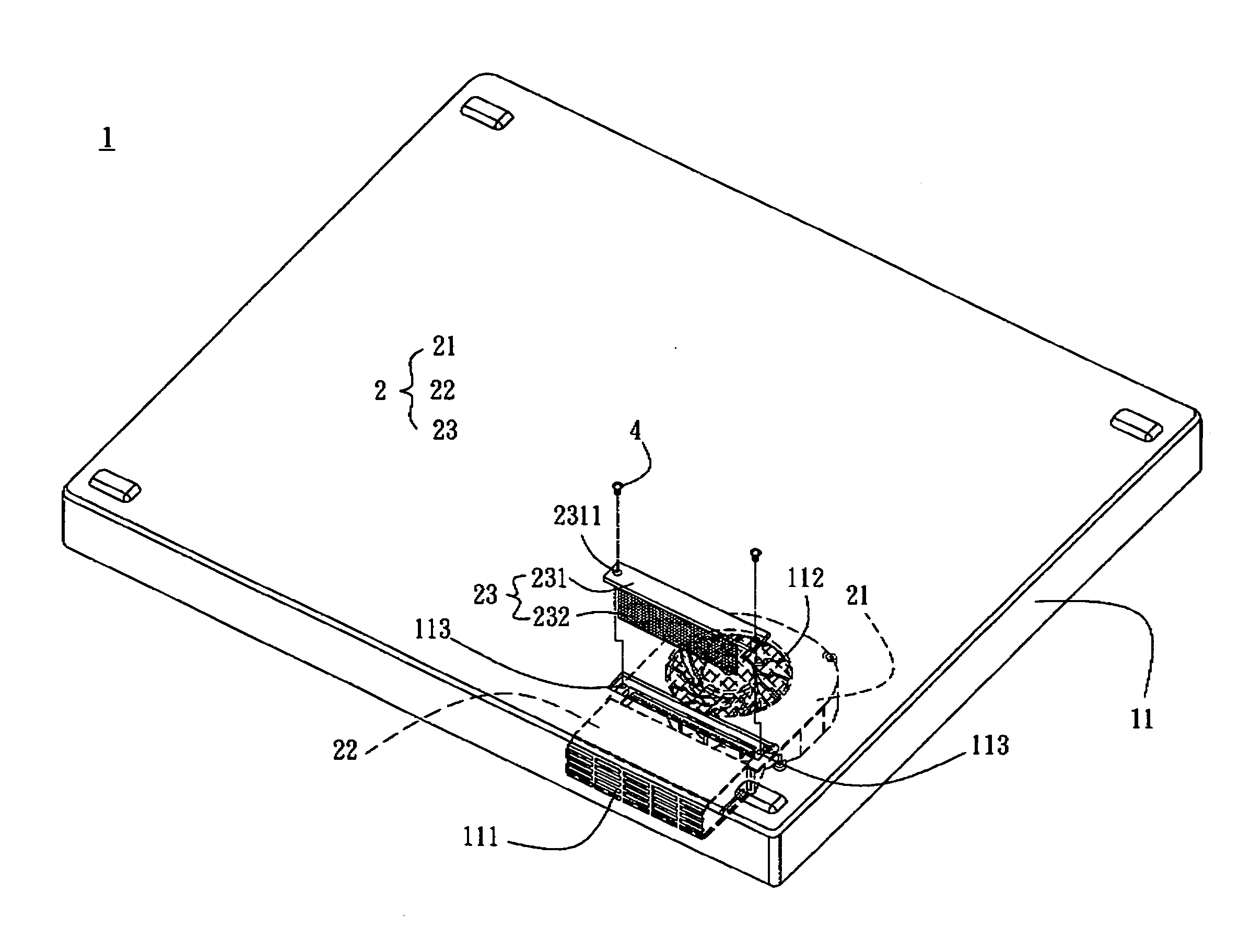
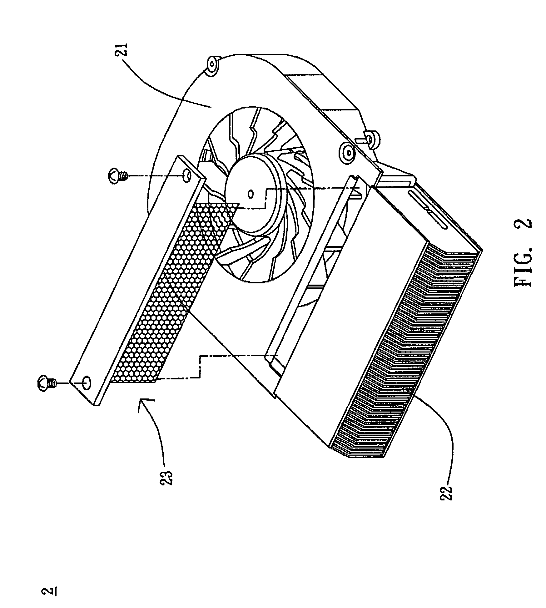
[0024]As shown in FIG. 2, a heat spreader 2 with a filtering function according to a preferred embodiment of the invention includes a heat sink set 22 and a filter unit 23. The heat spreader 2 is installed inside a case 11 of an electrical apparatus 1, as illustrated in FIG. 3.

[0025]With reference to FIG. 3, a fan 21 is installed inside the case 11. The case 11 further has a first opening 111 and a second opening 112. The first opening 111 is the outlet of the fan 21, and the second opening 112 is the inlet of the fan 21. The heat sink set 22 is installed inside the case 11 and is adjacent to the first opening 111. The filter unit 23 is installed inside the case 11 and is adjacent to the heat sink set 22. In this embodiment, the filter unit 23 is located between the fan 21 and the hea...


PUM


Abstract

A heat spreader with a filtering function is set in a case of an electrical apparatus. The heat spreader includes a heat sink set and a filter unit. The heat sink set is set in the case. The filter unit is set in the case and is adjacent to the heat sink set. In addition, an electrical apparatus includes a case and a filter unit, and a heat spreader is set in the electrical apparatus. The filter unit is set in the case and is adjacent to the heat spreader.

Description

BACKGROUND OF THE INVENTION[0001]1. Field of Invention[0002]The invention relates to a heat spreader and an electrical apparatus and, in particular, the invention relates to a heat spreader and an electrical apparatus with a filtering function.[0003]2. Related Art[0004]With the rapid development in the integrated circuit (IC) manufacturing technology, electronic elements have higher operating speeds. As a result, a huge amount of heat will be generated when electronic elements are running at high frequencies. If such heat is not removed, the temperature of the electronic element will continuously rise to reach a threshold temperature that affects the operation stability of the electronic element. More seriously, the electronic element may be burned out.[0005]An information processing device, such as an electrical apparatus, consists of many different electronic elements. Since the electrical apparatus is frequently used, many of its interior elements have low efficiency due to long-...

Claims


Application Information

Patent Timeline
Patent Type & Authority Patents(United States)
IPC IPC(8): H05K7/20F04D29/70H01L23/467
CPCF04D29/703H05K7/20181G06F1/203H01L23/467H01L2924/0002H01L2924/00
Inventor HUANG, HUANG-YUAN
Owner ASUSTEK COMPUTER INC
Why Eureka
Try Eureka