Diode mixer

a mixer and diode technology, applied in the direction of electromagnetic wave demodulation, modulation transference, electric apparatus, etc., can solve the problems of reducing the maximum attainable distance of signal light, requiring a good noise characteristic of the mixer, and reducing the s/n ratio, etc., to achieve good noise characteristic, simple configuration, and high frequency conversion efficiency

Active Publication Date: 2008-04-22
ARIGNA TECH LTD
View PDF11 Cites 6 Cited by
  • Summary
  • Abstract
  • Description
  • Claims
  • Application Information

AI Technical Summary

Benefits of technology

[0022]The present invention has been made to solve the above problem, and it is a first object to provide a diode mixer high in frequency conversion efficiency and good in noise characteristic in a simple configuration.
[0026]To this end, when the first signal whose power is increased to such an extent that the forward anode voltage amplitude of the first signal reaches near the built-in voltage of the first diode, is applied to the semiconductor section, parallel resonance occurs by means of the variable capacitive component and the inductor, so that leakage of input power with an increase in the capacitance of the variable capacitive component, which increases with an increase in the anode voltage, is suppressed, and the first signal is effectively inputted to the variable resistive component of the first diode that contributes to frequency conversion at the diode mixer, thereby making it possible to improve frequency conversion gain of the diode mixer.
[0027]Thus, the simple configuration that the first circuit element unit having such a circuit that the capacitor and the inductor are connected in series, is connected in parallel with the first diode, makes it possible to constitute a diode mixer satisfactory in noise characteristic, large in conversion gain for frequency conversion and high in frequency conversion efficiency.

Problems solved by technology

However, a mixer good in noise characteristic is required simultaneously.
For example, a communication laser device causes the disadvantages that when a mixer is unsatisfactory in noise characteristic, an S / N ratio is reduced and the maximum attainable distance of signal light is decreased, and the cost of a system increases in order to highly maintain the reliability of the system.
However, the mixer using the pn diode was reduced in frequency conversion efficiency in some instances due to the existence of a diffusion capacitance in the diode.
Therefore, a problem arises in that even though attempts are made to increase the power of the LO signal, increase the anode amplitude voltage of the LO signal and raise conversion gain for frequency conversion, the capacitive component of the diode increases exponentially and the power of the LO signal is not effectively inputted to the variable resistive component of the diode, which contributes to the frequency conversion at a mixer circuit, so that satisfactory frequency conversion efficiency is not obtained.

Method used


Image

  • Diode mixer
  • Diode mixer
  • Diode mixer

Examples


first embodiment

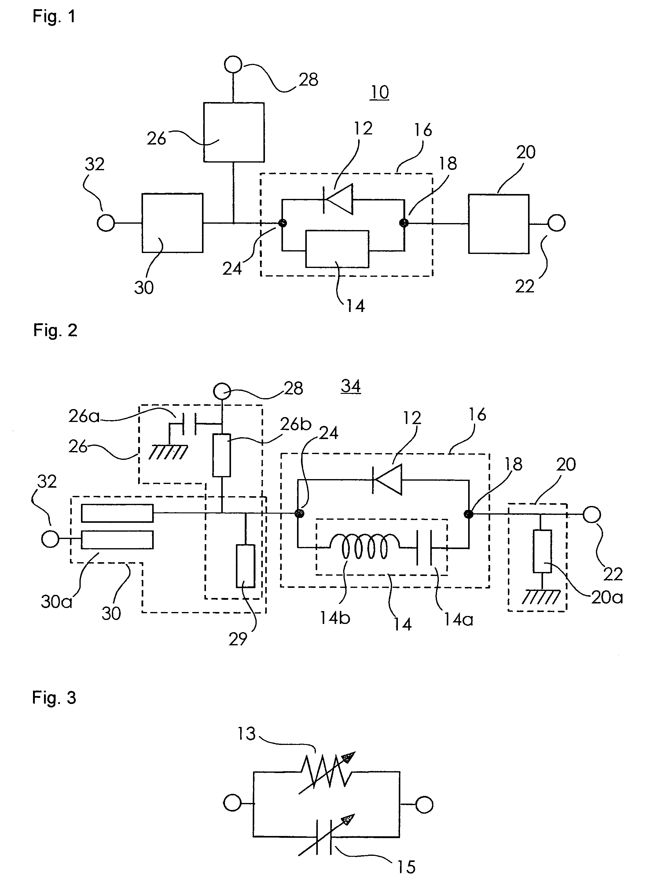
[0050]FIG. 1 is a block diagram of a diode mixer according to a first embodiment of the present invention.

[0051]Incidentally, the same reference numerals indicate the same or corresponding ones in respective figures.

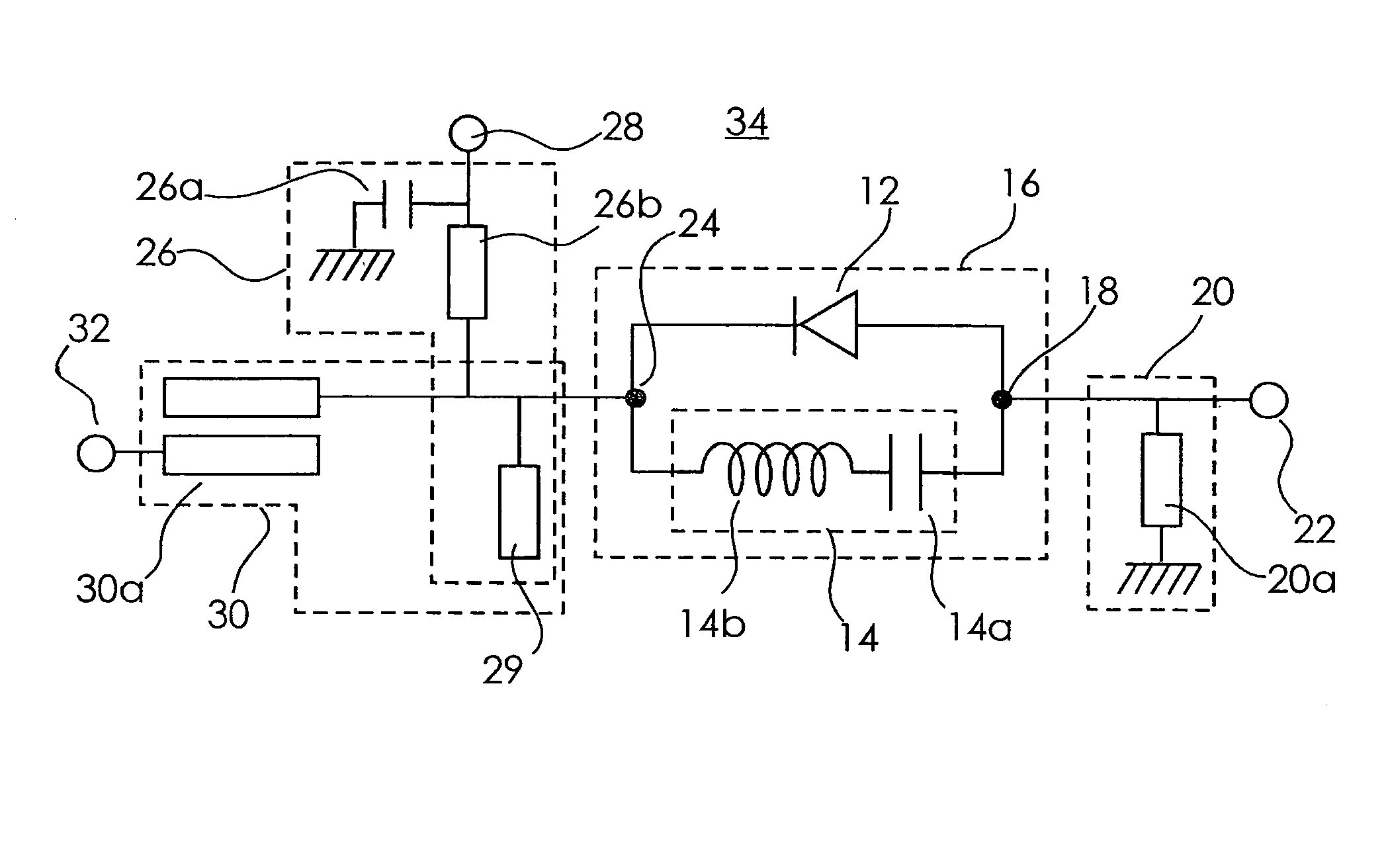
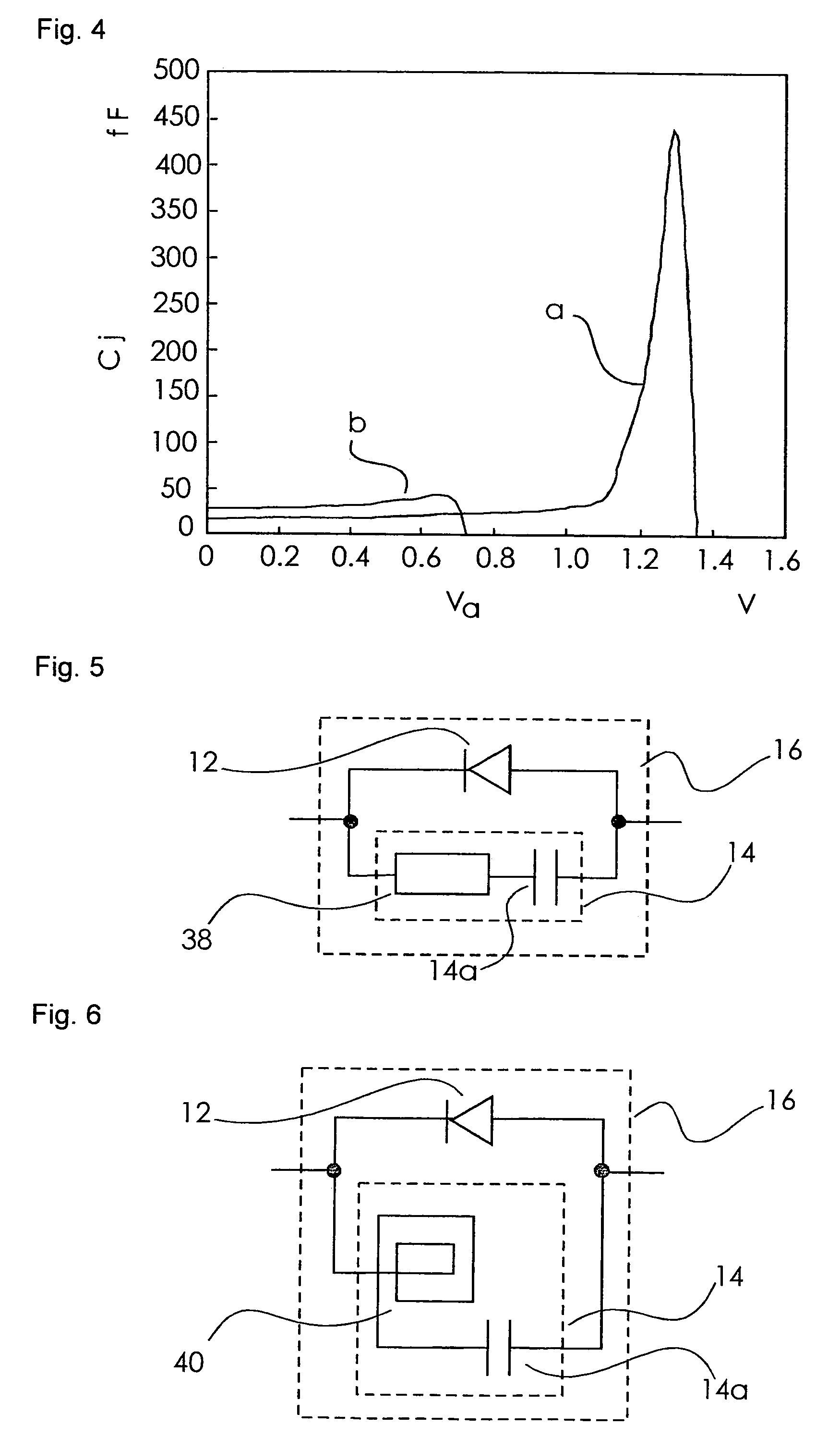
[0052]In FIG. 1, the diode mixer 10 is of a single-ended diode mixer and comprises a mixer diode section 16 serving as a semiconductor section, which comprises a diode 12 serving as a first diode and a first inductor circuit 14 serving as a first circuit element unit including an inductor and a capacitor parallel-connected to the diode 12 and connected in series with each other, an LO signal port 22 serving as a first signal input / output terminal, which is connected via a first branching circuit 20 to a first connecting portion 18 to which the anode of the diode 12 and the first inductor circuit 14 in the mixer diode section 16 are connected, an IF signal port 28 serving as a second signal input / output terminal, which is connected via a second branching circuit 26 to a s...

second embodiment

[0112]FIG. 12 is a block diagram of a diode mixer according to one embodiment of the present invention.

[0113]The diode mixer 60 is basically identical to the diode mixer 10 according to the first embodiment but different therefrom in that an antiparallel-connected diode 62 serving as a second diode is further added in addition to a diode 12 in a mixer diode section 16.

[0114]In FIG. 12, the diode 62 is connected in antiparallel with the diode 12. That is, the cathode of the diode 62 is connected to a first connecting portion 18, and the anode of the diode 62 is connected to a second connecting portion 24, respectively. Thus, a first inductor circuit 14 including an inductor and a capacitor connected in series is connected in parallel with the diode 12 and the diode 62 respectively.

[0115]Although there is shown an example in which a second branching circuit 26 and an IF signal port 28 are connected to the second connecting portion 24 in the diode mixer 60 in a manner similar to the di...

third embodiment

[0152]FIG. 16 is a block diagram of a diode mixer according to one embodiment of the present invention.

[0153]The diode mixer 70 shown in FIG. 16 is of a balance type diode mixer and further includes, in addition to a first mixer diode section 16, a second mixer diode section 77 including a diode 74 serving as a second diode, which is connected in antiparallel with a diode 12 of the first mixer diode section 16, and a second inductor circuit 76 serving as a second circuit element unit, which is connected in parallel with the diode 74.

[0154]The anode of the diode 74 of the second mixer diode section 77 and one end of the second inductor circuit 76 are connected to a second connecting portion 24 of the first mixer diode section 16, whereas the cathode of the diode 74 and the other end of the second inductor circuit 76 are connected to a third connecting portion 78.

[0155]And a first connecting portion 18 and the third connecting portion 78 are connected to an LO signal port 22 and an RF...


PUM


Abstract

A diode mixer comprises a mixer diode section which has a first circuit including an inductor and a capacitor connected in series and a diode connected in parallel with the first circuit and which includes a first connecting portion to which one end of the first circuit and the anode of the diode are connected, and a second connecting portion to which the other end of the first inductor circuit and the cathode of the diode are connected; an LO signal port connected to the first connecting portion via a first branching circuit and receiving an LO signal; an IF signal port connected to the mixer diode section via a second branching circuit; and an RF signal port connected to the mixer diode section through a third branching circuit. The inductor and the capacitive component of the diode constitute a resonant circuit.

Description

BACKGROUND OF THE INVENTION[0001]1. Field of the Invention[0002]The present invention relates to a diode mixer, and particularly to a diode mixer used in electronic equipment and microwave-band and millimeter-wave band communication apparatuses for mobile communications and wireless communications.[0003]2. Description of the related Art[0004]There has recently been an increasingly demand for small-sized and high-power apparatuses as communication apparatuses used in a microwave band and a millimeter wave band. With the demand thereof, there has been a demand for a mixer high in frequency conversion efficiency. However, a mixer good in noise characteristic is required simultaneously.[0005]For example, a communication laser device causes the disadvantages that when a mixer is unsatisfactory in noise characteristic, an S / N ratio is reduced and the maximum attainable distance of signal light is decreased, and the cost of a system increases in order to highly maintain the reliability of ...

Claims


Application Information

Patent Timeline
Patent Type & Authority Patents(United States)
IPC IPC(8): H04B1/26
CPCH03D9/0633H03D7/00H03D7/02
Inventor KANAYA, KOH
Owner ARIGNA TECH LTD
Why Eureka
Try Eureka