
Method for optimizing a link schedule

a link schedule and optimization technology, applied in the field of communication networks, can solve the problems of affecting the display call-up of operator stations, affecting the quality of the content of the link schedule, and restricting the scheduling to some degr

Inactive Publication Date: 2008-04-22
HONEYWELL INT INC
View PDF18 Cites 2 Cited by
  • Summary
  • Abstract
  • Description
  • Claims
  • Application Information

AI Technical Summary

Benefits of technology

The present invention provides a method for optimizing a mixed scheduled / unscheduled network schedule, particularly a FIELDBUS. The method prioritizes the scheduling of sequences of function blocks and minimizes delays during the scheduling process. By scheduling certain function blocks, in different devices, and positioning publications between them, the method reduces scheduled portion of the link schedule and increases application performance. The method is applicable to multi-processor devices and reduces bandwidth wasted by avoiding concurrent or partially concurrent publications.

Problems solved by technology

While Foundation FIELDBUS technology permits interactive communication among devices, scheduling is restricted to some degree.
Particularly when many devices are sharing a link, “natural order” scheduling tends to produce a large number of relatively “short” publication gaps.
These “short” gaps often reflect wasted bandwidth because large queued communications, and all communications queued behind them, are delayed until a large enough gap arises in the schedule.
For example, display call-ups and operator station display call-ups are often most severely affected since they typically require relatively large gaps to satisfy their heavy information transfer demands.
Accordingly, the number of client-server messages transmitted per macrocycle is limited, and less than optimum application performance is achieved.
“Natural order” scheduling also often yields relatively long schedules and frequently produces significant loop latencies.
Since large latencies reflect older samplings and ineffectual performance, their appearance in critical control applications is often a matter of great concern.

Method used


Image

  • Method for optimizing a link schedule
  • Method for optimizing a link schedule
  • Method for optimizing a link schedule

Examples


example 1

4.0 Example 1

Two Simple Loops, Control in Actuator

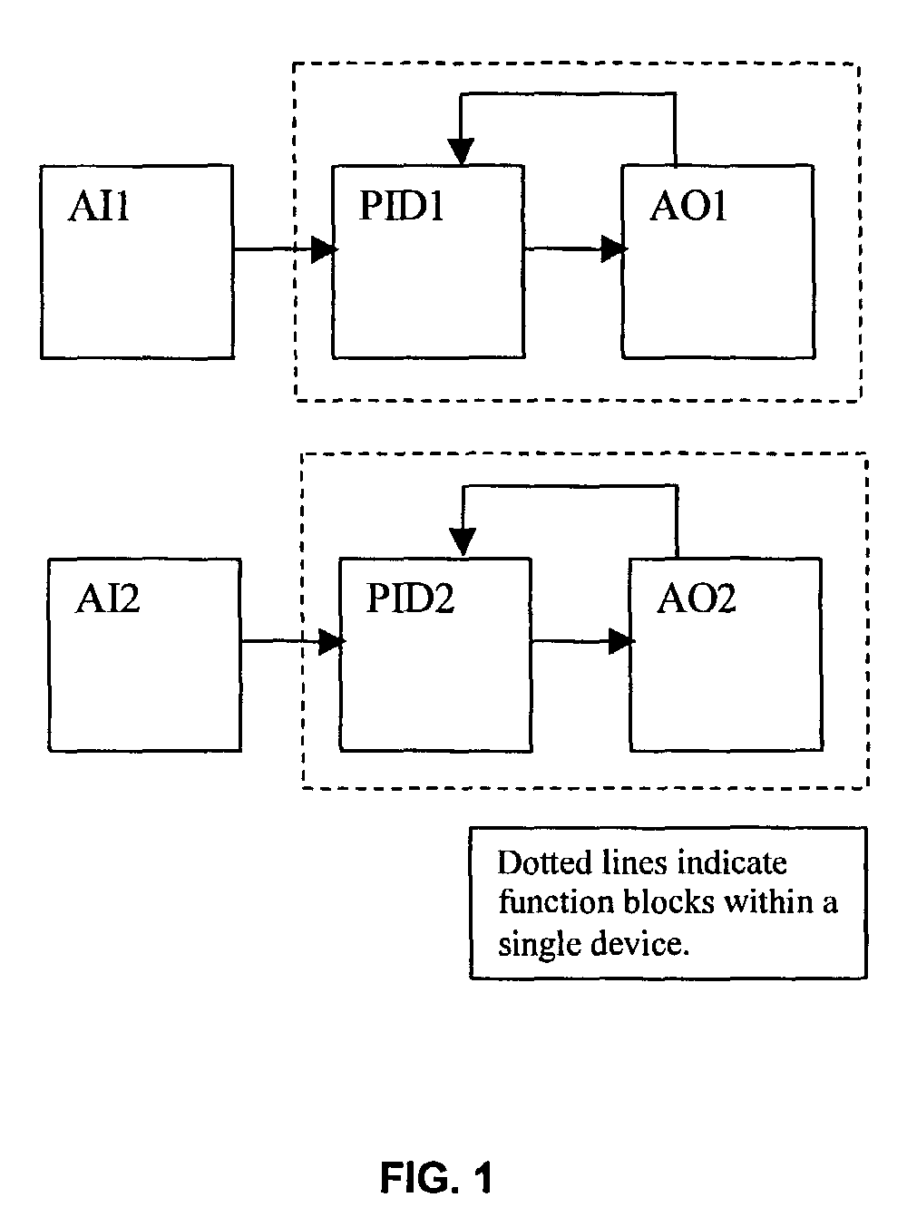
[0129]As shown in FIG. 1, when simple loop control is co-resident with the actuator, there is only one publication from the transmitter to the actuator for each loop.

4.1 Natural Link Schedule

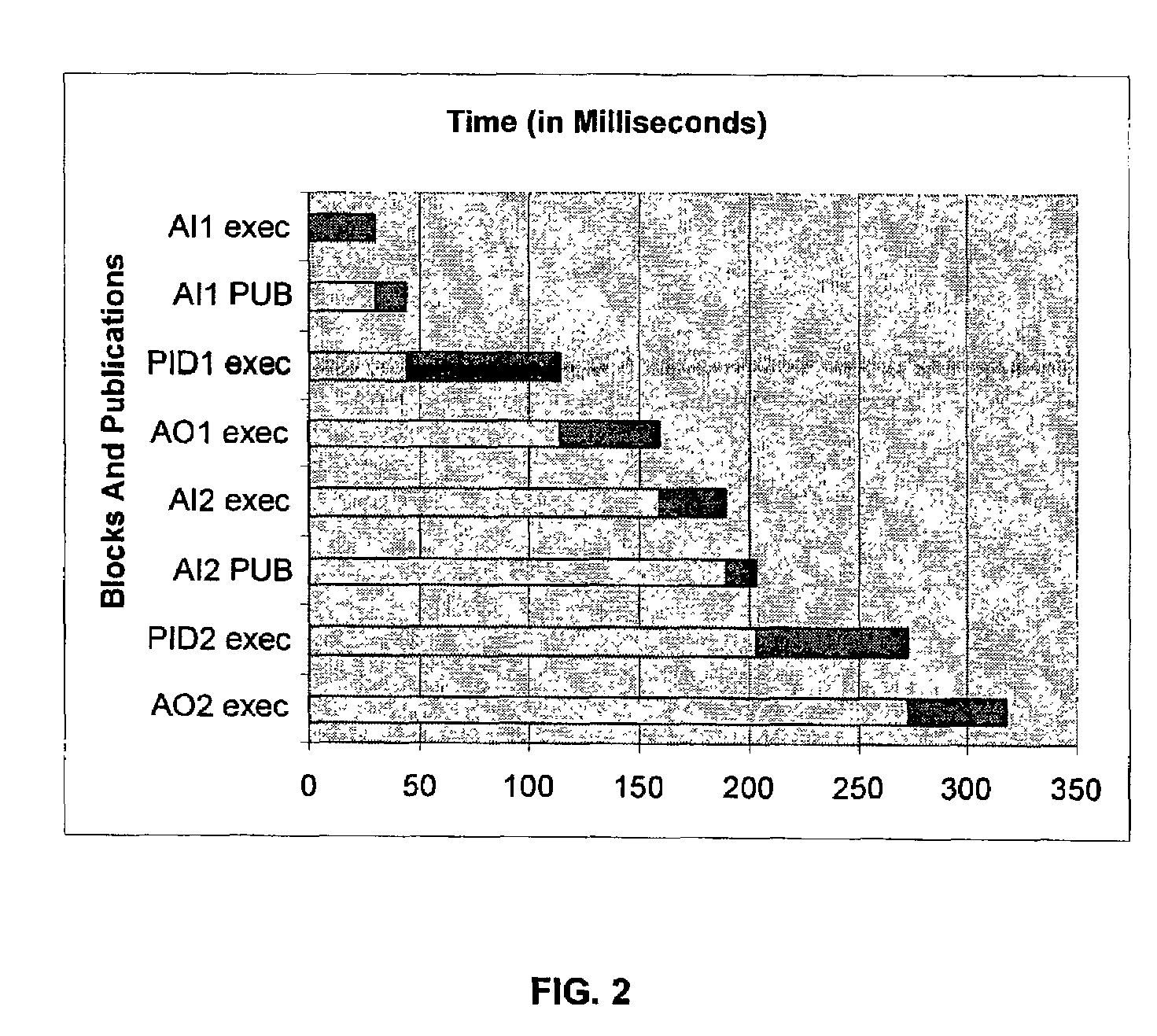
[0130]The natural link schedule set forth below, and reflected in FIG. 2, indicates that the blocks of the first loop are executed first, in natural sequence. The second loop sequences identically, but does not start until the first loop completes its execution in its entirety. (The time offsets are in milliseconds.)

[0131]

SchedulePubUsableFunctionStartLengthEndGapGapAI1 exec03030AI1 PUB301444827812PID1 exec4470114AO1 exec11445159AI2 exec15930189AI2 PUB18914203145130PID2 exec20370273AO2 exec27345318972942

4.2 Optimized Link Schedule

[0132]The optimized link schedule is set forth below and is reflected in FIG. 3. Under the assumption that the first sequence is assigned to the schedule before the second sequence, the second sequence is assigned via 3....

example 2

5.0 Example 2

Two Simple Loops, Control in Transmitter

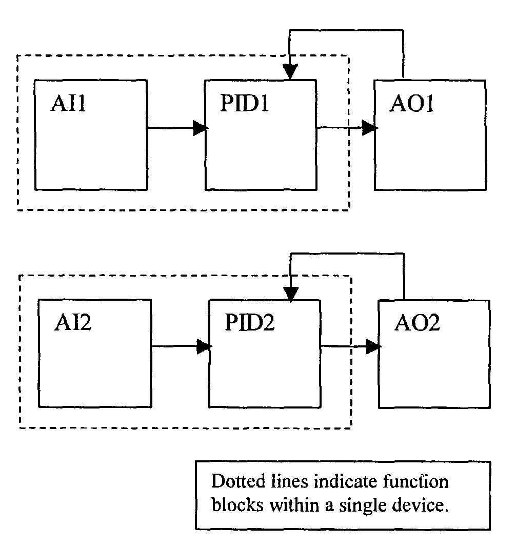
[0136]Although the functionality is identical to the previous example (two simple control loops), the link scheduling differs. When simple loop control is co-resident with the transmitter, there are two publications: one, the output from the controller to the actuator, and a second, the back-calculation parameter from the actuator back to the controller. As indicated in FIG. 4, these occur for each of the two loops.

5.1 Natural Link Schedule

[0137]As indicated below, and as reflected in FIG. 5, the natural link schedule executes the blocks of the first loop first with the publication of the PID1's output done as soon as the value is calculated, and the back-calculation of the actuator published as soon as it is available. The second loop sequences identically, but does not start until the first loop completes its execution in its entirety, including the back-calculation.

[0138]

SchedulePubUsableFunctionStartLengthEndGapGapAI1 exec0303...

example 3

6.0 Example 3

Triple Signal Selector

[0144]When triple redundant inputs are used, an input-selector block chooses one—or the average of some or all of the inputs-depending on the goals of the configuration. FIG. 7 sets forth an example using a triple signal selector.

6.1 Natural Link Schedule

[0145]As shown below, and as reflected in FIG. 8, the natural link schedule executes the first AI block that immediately publishes its output. Then, the second AI block is executed, publishing its output immediately. Next, the third AI block is executed, publishing its output immediately. Finally, the Input-Selector block executes, followed by the PID and AO blocks.

[0146]

SchedulePubUsableFunctionStartLengthEndGapGapAI1 exec03030AI1 PUB301444898883AI2 exec443074AI2 PUB741488300AI3 exec8830118AI3 PUB11814132300ISel exec13230162PID exec16270232AO exec23245277958883

6.2 Optimized Link Schedule

[0147]To minimize skew, “No-Sample-Skew” can be selected and all three values can be simultaneously sampled in t...


PUM


Abstract

A method for improving a link schedule used in a communications network is disclosed. While the method applies generally to networks that operate on a scheduled communications basis, it is described in the context of a Foundation FIELDBUS. The method includes: scheduling sequences and their associated publications according to their relative priority, per application; minimizing delays between certain function blocks, and between certain function blocks and publications; and grouping certain publications. Accordingly, advantages such as latency reduction, schedule length reduction, and improved communications capacity are gained.

Description

BACKGROUND OF THE INVENTION[0001]1. Field of the Invention[0002]The invention relates generally to communications networks and more particularly to communications networks that operate on a periodically executed schedule.[0003]2: Discussion of the Related Art[0004]FOUNDATION™ FIELDBUS technology is an open technology provided by the FIELDBUS Foundation of Austin, Tex., U.S.A. It is a local area network type of communications BUS based on the International Electro-Technical Commission 61158 FIELDBUS standard. That standard calls for some of the periodic communications on the BUS to be scheduled within a periodically executed schedule.[0005]While Foundation FIELDBUS technology permits interactive communication among devices, scheduling is restricted to some degree. For instance, only one function block in a single application processor device may execute at a time. Further, only one device may publish (that is, a publication or back-calculation publication) on the link at a time, and ...

Claims


Application Information

Patent Timeline
Patent Type & Authority Patents(United States)
IPC IPC(8): G06F15/16H04L12/56
CPCH04L2012/4026H04L2012/40208H04L47/28H04L47/283H04L47/2475H04L47/24H04L12/40G06F15/16G06F9/46H04L12/5601A01K15/025
Inventor HODSON, WILLIAM R.
Owner HONEYWELL INT INC
Learn More