Vehicle air conditioning system

a vehicle air conditioning and passenger compartment technology, applied in the field of vehicle air conditioning systems, can solve the problems that the effectiveness of the vehicle air conditioning system can sometimes be insufficient to adequately cool the passenger compartment of the vehicle, and achieve the effect of increasing the cooling capacity of the system

Inactive Publication Date: 2008-04-29
NISSAN MOTOR CO LTD
View PDF13 Cites 43 Cited by
  • Summary
  • Abstract
  • Description
  • Claims
  • Application Information

AI Technical Summary

Benefits of technology

[0007]It has been discovered that adding intercooling to an air conditioning system can increase the cooling capacity of the system.
[0008]One object of the present invention is to provide an air conditioning system that improves the effectiveness of intercooling.
[0009]Another object of the present invention is to provide an air conditioning system that has increased the cooling capacity without costly modification to the vehicle air conditioning system.

Problems solved by technology

However, in peak load conditions, such as extremely high ambient temperature conditions, the effectiveness of the vehicle air conditioning system can sometimes be insufficient to adequately cool the passenger compartment of the vehicle even with such intercooling.

Method used


Image

  • Vehicle air conditioning system
  • Vehicle air conditioning system
  • Vehicle air conditioning system

Examples


second embodiment

[0057]Referring now to FIG. 7, a portion of a vehicle air conditioning system 12′ in accordance with a second embodiment will now be explained. In view of the similarity between the first and second embodiments, the parts of the second embodiment that are identical to the parts of the first embodiment will be given the same reference numerals as the parts of the first embodiment. Moreover, the descriptions of the parts of the second embodiment that are identical to the parts of the first embodiment may be omitted for the sake of brevity. The parts of the second embodiment that differ from the parts of the first embodiment will be indicated with a single prime (′).

[0058]In the second embodiment, all the portions of the vehicle air conditioning system 12′ are generally the same as the vehicle air conditioning system 12 of the first embodiment, except that the second high pressure tube 30, the low pressure tube 32 and the thermoelectric device 14 are replaced in the second embodiment w...

third embodiment

[0060]Referring now to FIG. 8, a portion of a vehicle air conditioning system 12″ in accordance with a third embodiment will now be explained. In view of the similarity between the first and third embodiments, the parts of the third embodiment that are identical to the parts of the first embodiment will be given the same reference numerals as the parts of the first embodiment. Moreover, the descriptions of the parts of the third embodiment that are identical to the parts of the first embodiment may be omitted for the sake of brevity. The parts of the third embodiment that differ from the parts of the first embodiment will be indicated with a double prime (″).

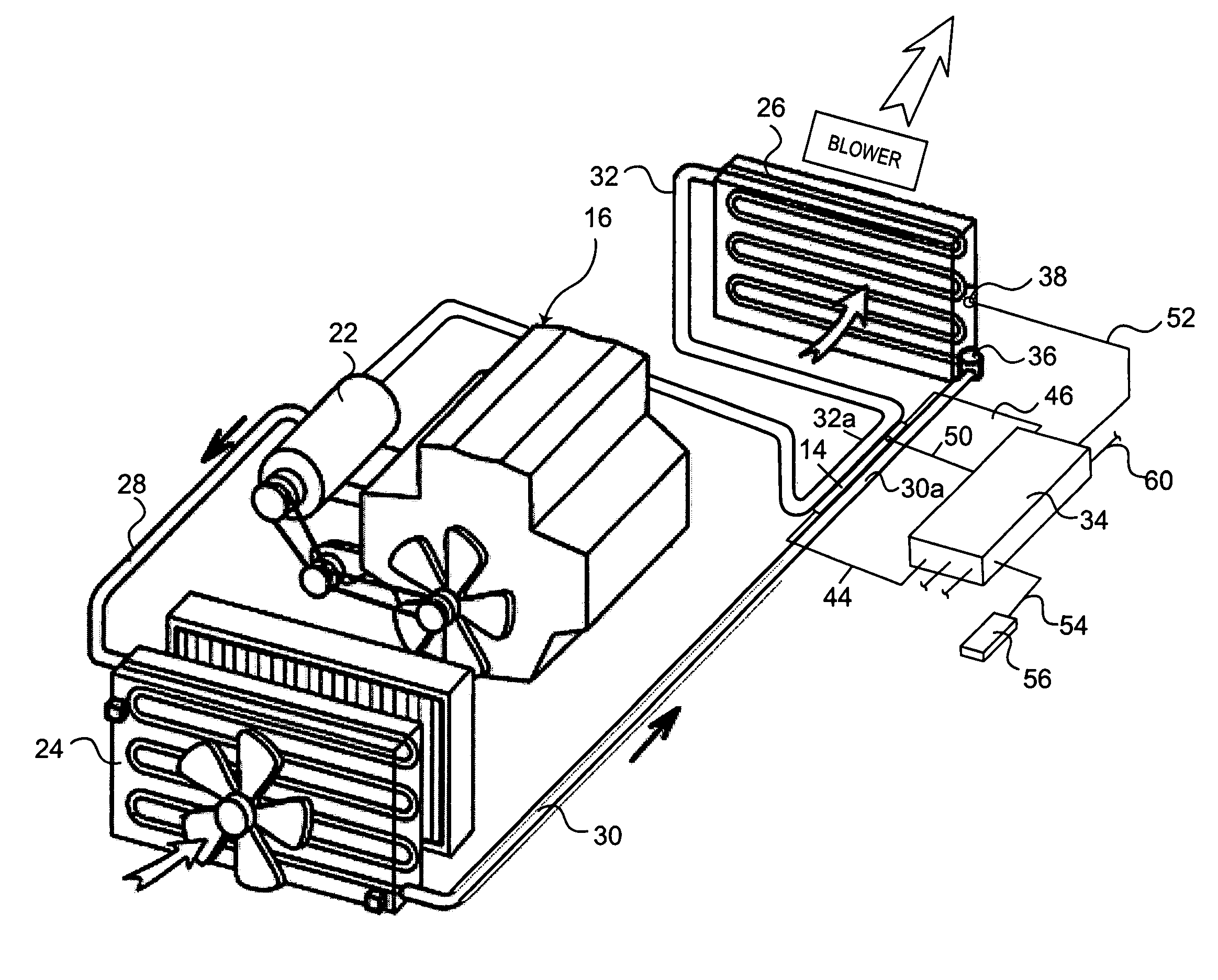
[0061]The third embodiment includes the thermoelectric device 14, the compressor 22, the condenser 24, the evaporator 26, the first high pressure tube 28, the second high pressure tube 30 and the controller 34 (not shown in FIG. 8). These components are generally the same or identical to the similarly named components of the fir...

fourth embodiment

[0062]Referring now to FIG. 9, a portion of a vehicle air conditioning system 12′″ in accordance with a fourth embodiment will now be explained. In view of the similarity between the prior embodiments and this fourth embodiment, the parts of the fourth embodiment that are identical to the parts of the prior embodiments will be given the same reference numerals as the parts of the prior embodiments. Moreover, the descriptions of the parts of the fourth embodiment that are identical to the parts of the prior embodiments may be omitted for the sake of brevity.

[0063]The fourth embodiment includes the thermoelectric device 14, the compressor 22, the condenser 24, the evaporator 26, the first high pressure tube 28, the second high pressure tube 30 and the controller 34 (not shown in FIG. 8). These components are generally the same or identical to the similarly named components of the first embodiment. However, in the fourth embodiment, the low pressure tube 32″ of the third embodiment is ...


PUM


Abstract

A vehicle air conditioning system includes a compressor, a condenser, an evaporator and a thermoelectric device. The compressor is configured to receive a refrigerant and compress the refrigerant to a compressed state. The condenser is in fluid communication with the compressor to receive the refrigerant in the compressed state via a high pressure tube. The evaporator is in fluid communication between the condenser and the compressor to receive the refrigerant from the condenser and convey the refrigerant to the compressor via a low pressure tube. The thermoelectric device is operatively arranged relative to at least a portion of the high pressure tube to remove heat from the high pressure tube.

Description

BACKGROUND OF THE INVENTION[0001]1. Field of the Invention[0002]The present invention generally relates to a vehicle air conditioning system. More specifically, the present invention relates to a vehicle air conditioning system provided with intercooling to a high pressure portion.[0003]2. Background Information[0004]A typical vehicle air conditioning system includes a compressor, a condenser, an expansion valve or orifice tube, and an evaporator. The compressor compresses a cool vapor-phase refrigerant (e.g., Freon, R134a) to heat the same, resulting in a hot, high-pressure vapor-phase refrigerant. This hot vapor-phase refrigerant runs through a condenser, typically a coil that dissipates heat. The condenser condenses the hot vapor-phase refrigerant into liquid refrigerant. The liquid refrigerant is throttled through an expansion valve, which evaporates the refrigerant to a cold, low-pressure saturated liquid-vapor-phase refrigerant. This cold saturated liquid-vapor-phase refrigera...

Claims


Application Information

Patent Timeline
Patent Type & Authority Patents(United States)
IPC IPC(8): F25B21/02
CPCB60H1/00885F25B25/00F25B40/00F25B49/02B60H2001/00949B60H2001/00957F25B21/02F25B2700/2117
Inventor EISENHOUR, RONALD
Owner NISSAN MOTOR CO LTD
Why Eureka
Try Eureka