
Slurry spreader for cementitious board production

a cementitious board and slurry spreader technology, applied in the direction of water-setting substance layered product, turning machine accessories, drawing profiling tools, etc., can solve the problem of difficult uniform distribution, limited control of the thickness of the screeding device, and difficulty in achieving the effect of reducing the water to cementitious material ratio, facilitating the use of less water, and reducing the number of undesirable large gaps

Inactive Publication Date: 2008-04-29
UNITED STATES GYPSUM CO
View PDF42 Cites 96 Cited by
  • Summary
  • Abstract
  • Description
  • Claims
  • Application Information

AI Technical Summary

Benefits of technology

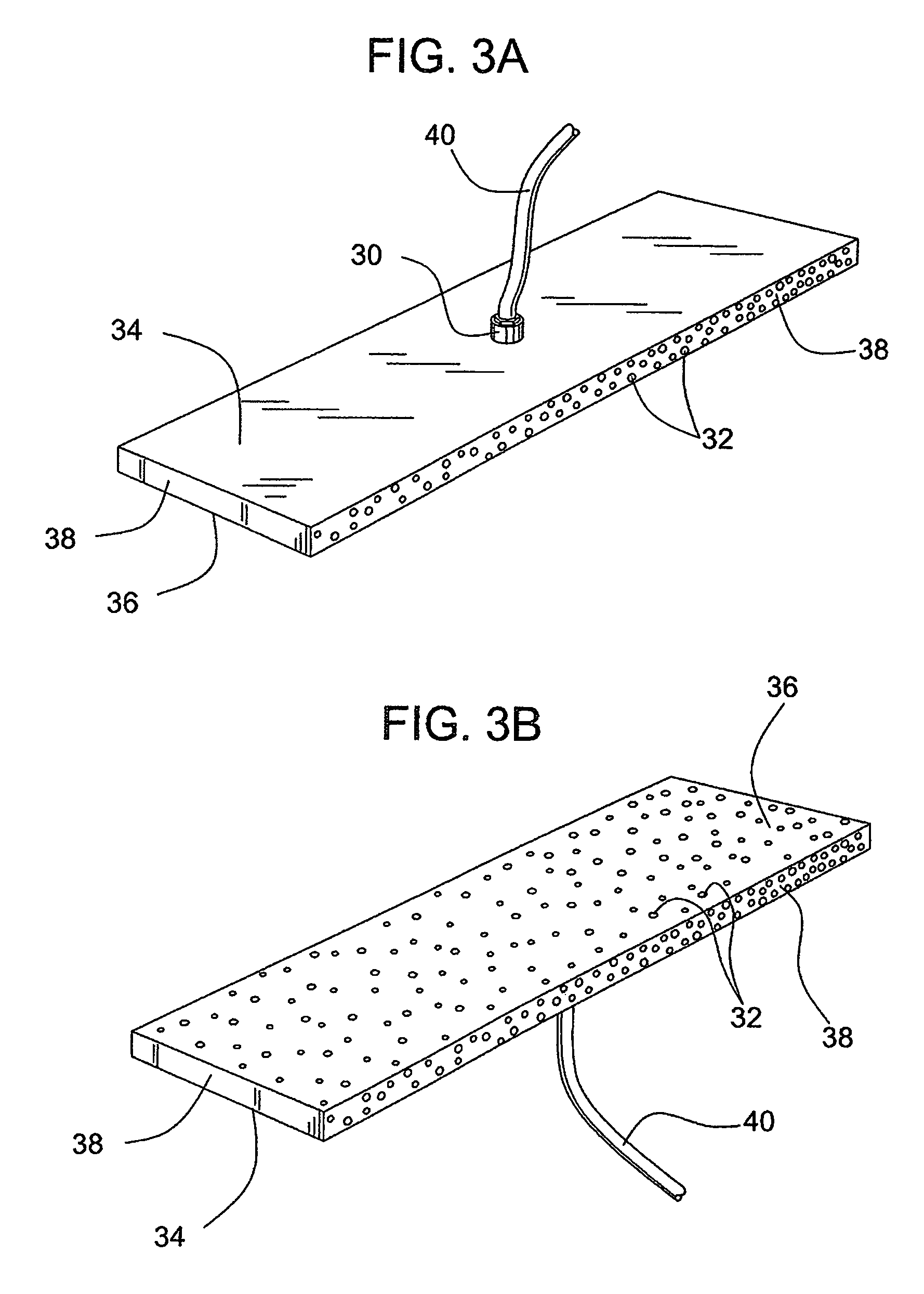
The present invention is a slurry spreader that is used to spread cementitious slurry on a moving backing layer in a board production process. The slurry spreader has a plurality of apertures that allow fluid to flow out of the slurry spreader and continuously flow across the surface of the slurry spreader. This results in improved production of cementitious board products, including reduced water usage, the elimination of large voids, and improved mechanical spreading and shaping of the slurry. The invention also provides a method of reducing the water to cementitious material ratio and the number of undesirable large voids during cementitious board production. Overall, the invention enhances the quality and efficiency of cementitious board production.

Problems solved by technology

Control of the thickness by means of screeding devices is limited by the flow properties of the hydraulic cement mixture.
Cementitious slurries are usually thixotropic but often do not yield quickly enough to a screed laid across a fast moving conveyor belt to be spread evenly.
Irregularity in the amount of slurries deposited on a fast moving conveyor belt tends to cause unevenness in the so-called “cement boards” and other building panels manufactured on high-speed production lines.
The wider the panel, the more difficult is the problem of even distribution of the slurry.
However, the presence of large amounts of water is undesirable inasmuch as it must be removed before the final board product is obtained.
Water removal is costly because of the energy required to evaporate the water and / or the time required to evaporate the water.
In addition, depending on the speed of the slurry being discharged, the cementitious slurry exiting the mixer can be turbulent such that undesirably large voids (e.g., voids having a diameter of 5 mm or greater) are formed as the slurry contacts the moving support surface.
The presence of such large voids is undesirable during board production because it compromises the quality of the resulting board, including, for example, the strength of the board and the score and snap properties, and can lead to formation of blisters.
In the case of cement board, rollers and other devices have been used to spread out the slurry; however, such rollers and devices can suffer from slurry build up which requires them to be continuously cleaned during board production.
Continuous cleaning creates a risk that a piece of built up set cement will fall off the rollers and other spreading devices and break the backing paper, or, in some applications, the release paper, thereby requiring complete shut down of the line.
Interruption of a board production line is costly and inefficient.

Method used


Image

  • Slurry spreader for cementitious board production
  • Slurry spreader for cementitious board production
  • Slurry spreader for cementitious board production

Examples


Embodiment Construction

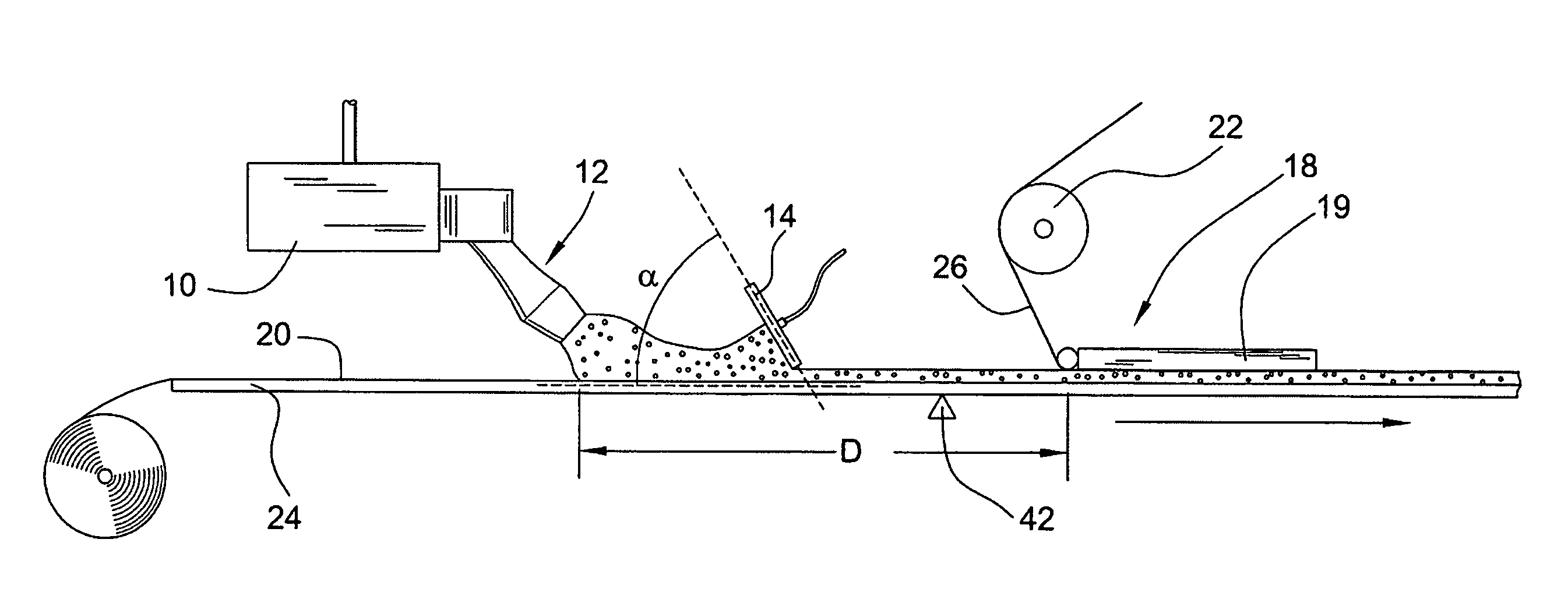
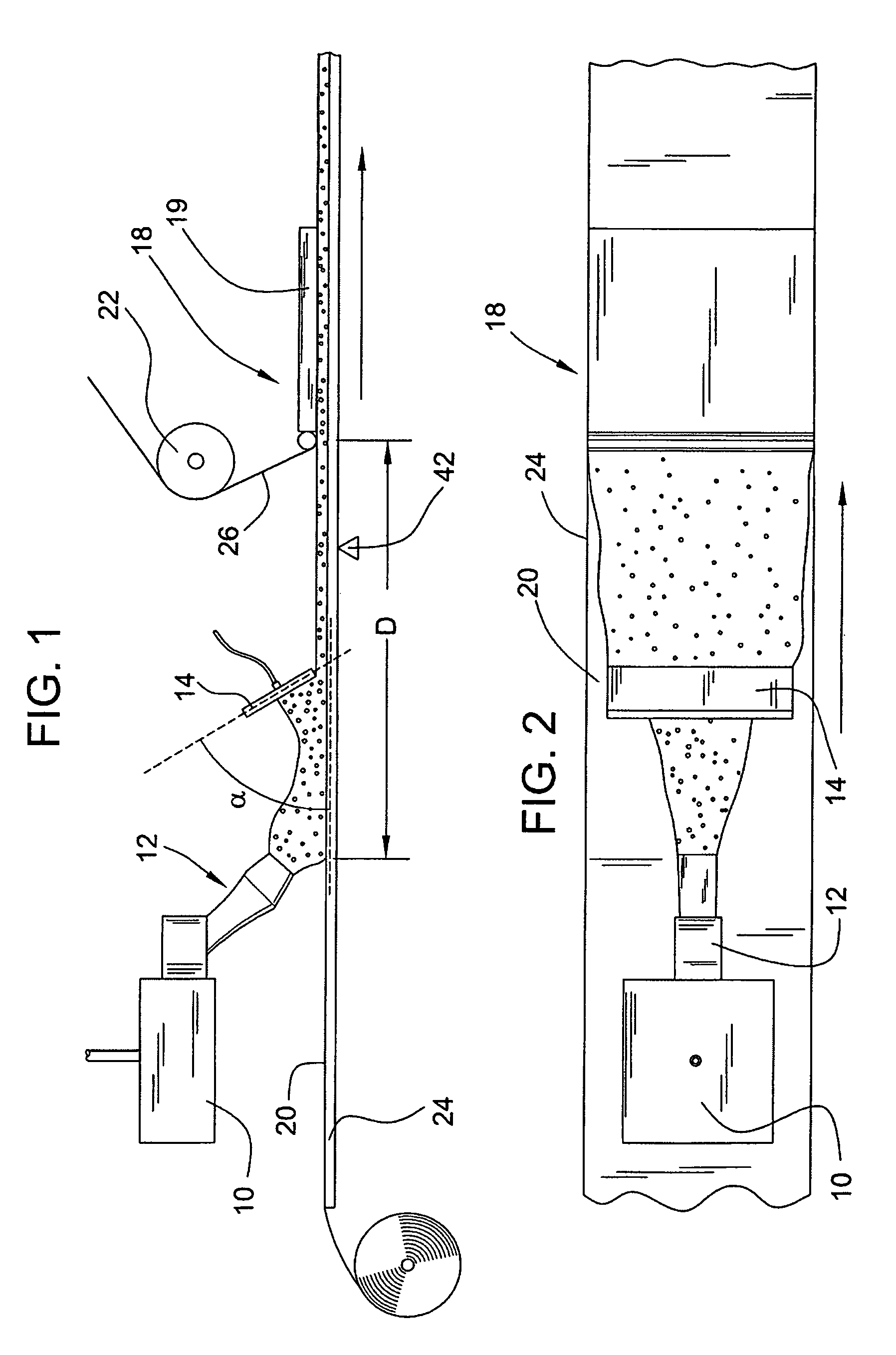
[0020]Turning to FIGS. 1 and 2, a board forming system 1 includes a mixer 10 with a discharge outlet 12, a slurry spreader 14, a forming station 18, a backing layer 20, an optional cover layer roll 22, and preferably a forming table with a conveyor 24 to facilitate the continuous production of cementitious board product. In operation, cementitious slurry used for forming the core of the board is prepared in mixer 10 and discharged through discharge outlet 12 directly or indirectly onto backing layer 20. The discharge outlet (or depositing mechanism) can be any suitable discharge outlet. For example, suitable slurry discharge outlets are described in U.S. Pat. No. 6,874,930, which is incorporated by reference herein. The slurry from the mixer can be deposited directly onto the backing paper, although in some embodiments, the slurry from the mixer is deposited indirectly onto the backing layer, such as for example, onto a densified layer. In a preferred embodiment of the invention, su...


PUM

PropertyMeasurementUnit
lengthaaaaaaaaaa
angleaaaaaaaaaa
angleaaaaaaaaaa

Abstract

The invention provides a board forming system comprising a forming table comprising a belt with a surface for conveying a backing layer; a mixer fitted with a mechanism capable of depositing cementitious slurry material over a top surface of the backing layer; and a slurry spreader positioned downstream of the mixer, wherein a portion of the slurry spreader comprises a plurality of apertures which are connected to a source of pressurized fluid. The slurry spreader is configured such that the pressurized fluid flows out of the slurry spreader through the apertures so as to provide a continuous film of fluid across an outer surface of the slurry spreader. The slurry spreader is positioned such that it can contact at least a portion of the cementitious slurry after the slurry exits the discharge and before the slurry is spread across the width of the backing layer such that the thickness of the slurry is approximately equal to the desired slurry thickness for board formation. The invention further provides methods for forming cementitious board comprising the use of the slurry spreader.

Description

BACKGROUND OF THE INVENTION[0001]The present invention relates generally to a cementitious board system and to methods for producing cementitious board.[0002]The use of cementitious materials, such as, but not limited to, calcium sulfate material and Portland cement, is well known in the art for inclusion in various products such as wallboard, acoustical panels, and cement board. A substantially uniform thickness across the length and width of such cementitious boards or panels is desirable for their use in side-by-side arrays on walls, ceilings, or floors. Control of the thickness by means of screeding devices is limited by the flow properties of the hydraulic cement mixture. Cementitious slurries are usually thixotropic but often do not yield quickly enough to a screed laid across a fast moving conveyor belt to be spread evenly. Irregularity in the amount of slurries deposited on a fast moving conveyor belt tends to cause unevenness in the so-called “cement boards” and other build...

Claims


Application Information

Patent Timeline
Patent Type & Authority Patents(United States)
IPC IPC(8): B28B1/16B28B13/02
CPCB28B19/0092B32B13/02B32B13/04B32B13/06B32B13/08B32B13/14B32B37/24B32B15/20B32B2607/00B32B2250/03B32B2250/40B32B2262/0276B32B2262/101B32B2315/06B32B1/00B32B3/00B32B37/00
Inventor SUCECH, STEVEN W.ENGLERT, MARK H.FRANK, WILLIAM A.MLINAC, RAYMOND JOHNVEERAMASUNENI, SRINIVAS
Owner UNITED STATES GYPSUM CO
Learn More