Method and apparatus for vibration detection

a technology of vibration detection and method, applied in the field of vibration detection, can solve the problems of affecting the operation of a system, primarily affecting the rotation and primarily affecting the translational vibration of proximity detectors

Active Publication Date: 2008-04-29
ALLEGRO MICROSYSTEMS INC
View PDF61 Cites 106 Cited by
  • Summary
  • Abstract
  • Description
  • Claims
  • Application Information

AI Technical Summary

Problems solved by technology

For example, when used in an automobile transmission, during starting of the automobile engine, the proximity detector primarily tends to experience rotational vibration, which tends to generate magnetic field signals having a first wave shape.
In contrast, during engine idle, the proximity detector primarily tends to experience translational vibration, which tends to generate magnetic field signals having a second wave shape.
It may be adverse to the operation of a system, for example, an automobile system in which the proximity detector is used, for the system to interpret an output signal from the proximity detector to be associated with a rotation in normal operation when only a vibration is present.
Therefore, the antilock brake system might not operate as intended.
It may also be undesirable to perform the above-described proximity detector calibration in response to a vibration rather than in response to a rotation in normal operation.
Since the conventional proximity detector cannot distinguish a magnetic field signal generated in response to a rotation in normal operation from a magnetic field signal generated in response to a vibration, the proximity detector may perform calibrations at undesirable times when experiencing the vibration, and therefore, result in inaccurate calibration.

Method used


Image

  • Method and apparatus for vibration detection
  • Method and apparatus for vibration detection
  • Method and apparatus for vibration detection

Examples


Embodiment Construction

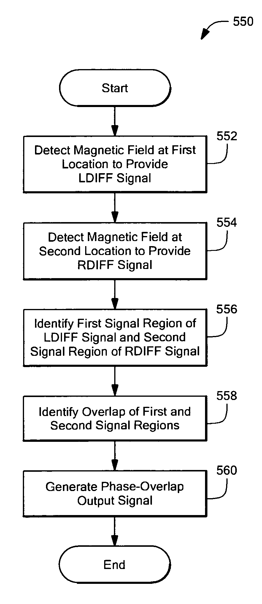
[0047]Before describing the present invention, some introductory concepts and terminology are explained. As used herein, the term “rotational vibration” refers to a back and forth rotation of an object about an axis of rotation, which object is adapted to rotate in a unidirectional manner about the axis of rotation in normal operation. As used herein, the term “translational vibration” refers to translation of the object and / or of magnetic field sensors used to detect magnetic fields generated by the object generally in a direction perpendicular to the axis of rotation. It should be recognized that both rotational vibration and translational vibration can cause signals to be generated by the magnetic field sensors.

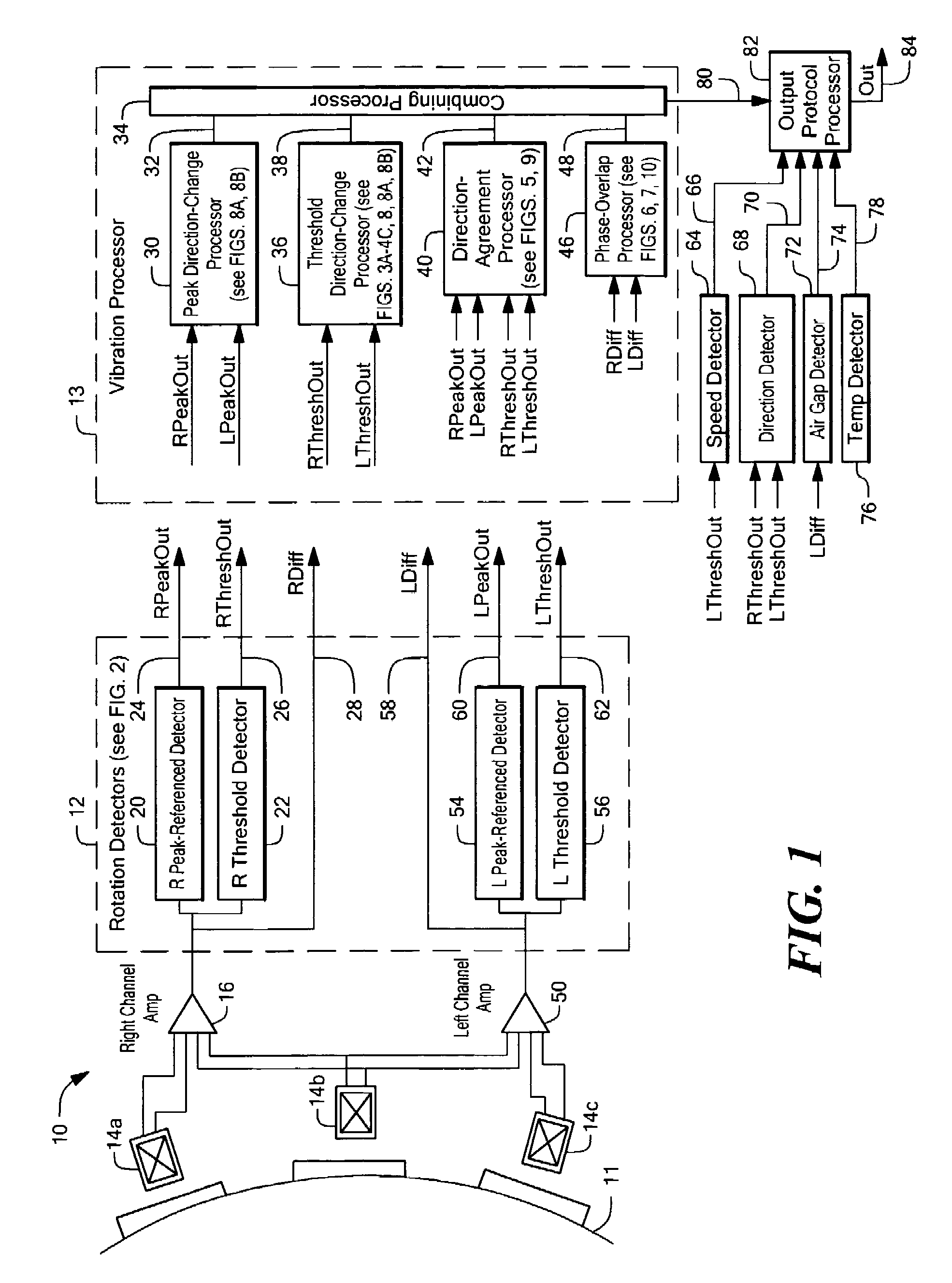
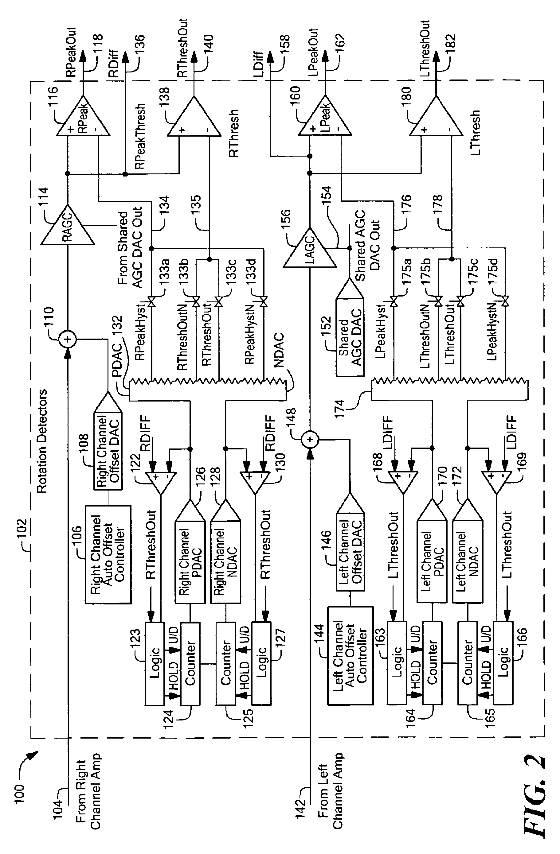
[0048]Referring now to FIG. 1, an exemplary sensor 10 includes a plurality of magnetic field sensors 14a-14c for generating an RDIFF signal 28 proportional to a magnetic field at a first location relative to an object 11 and an LDIFF signal 58 proportional to a magnetic fi...


PUM


Abstract

Apparatus for detecting vibration of an object adapted to rotate includes one or more vibration processors selected from: a direction-change processor adapted to detect changes in a direction of rotation of the object, a direction-agreement processor adapted to identify a direction of rotation of the object in at least two channels and identify an agreement or disagreement in direction of rotation identified by the at least two channels, a phase-overlap processor adapted to identify overlapping signal regions in signals associated with the rotation of the object, and a running mode processor adapted to identify an unresponsive output signal from at least one of the at least two channels. A method for detecting the vibration of the object includes generating at least one of a direction-change output signal with the direction-change processor, a direction-agreement output signal with the direction-agreement processor, a phase-overlap output signal with the phase-overlap processor, and a running-mode-vibration output signal with the running-mode processor, each indicative of the vibration the object.

Description

CROSS REFERENCE TO RELATED APPLICATIONS[0001]This application is a Continuation-In-Part of and claims the benefit under 35 U.S.C. §120 of U.S. patent application Ser. No. 10 / 820,957 filed Apr. 8, 2004, which application is incorporated herein by reference in its entirety.STATEMENT REGARDING FEDERALLY SPONSORED RESEARCH[0002]Not Applicable.FIELD OF THE INVENTION[0003]This invention relates generally to vibration detection, and in particular, to vibration detection methods and apparatus that can identify a vibration in an object adapted to rotate in normal operation.BACKGROUND OF THE INVENTION[0004]Proximity detectors (also referred to herein as rotation detectors) for detecting ferrous or magnetic objects are known. One application for such devices is in detecting the approach and retreat of each tooth of a rotating ferrous object, such as a ferrous gear. The magnetic field associated with the ferrous object is often detected by one or more magnetic field-to-voltage transducers (also...

Claims


Application Information

Patent Timeline
Patent Type & Authority Patents(United States)
IPC IPC(8): G01B7/14G01B7/00G01B7/30G01H1/00G01R33/025
CPCG01H1/003G01R33/025G01D5/2451G01D2205/85
Inventor BAILEY, JAMES M.DOOGUE, MICHAEL C.TOWNE, JAY M.
Owner ALLEGRO MICROSYSTEMS INC
Why Eureka
Try Eureka