
Heat sink tab for optical sub-assembly

a technology of optical sub-assembly and sink tab, which is applied in the direction of optical elements, electrical apparatus casings/cabinets/drawers, instruments, etc., can solve the problems of increasing undesirable heat, which must be removed, and achieve the effect of reducing the amount of hea

Active Publication Date: 2008-04-29
LUMENTUM OPERATIONS LLC
View PDF9 Cites 54 Cited by
  • Summary
  • Abstract
  • Description
  • Claims
  • Application Information

AI Technical Summary

Benefits of technology

The present invention is about an opto-electronic device that converts optical signals to electrical signals or vice versa. It includes an optical sub-assembly, a housing with a heat-dissipating cover, and a thermally conductive heat sinking tab that helps transfer heat from the optical sub-assembly to the cover. The technical effect of this invention is that it helps to efficiently dissipate the heat generated by the optical sub-assembly, which can improve the performance and reliability of the opto-electronic device.

Problems solved by technology

Increasing data rates, e.g. in excess of 10 Gb, required by the latest optical transceivers, causes in an increase in power dissipation by the active components therein resulting in an increase in undesirable heat, which must be removed.

Method used


Image

  • Heat sink tab for optical sub-assembly
  • Heat sink tab for optical sub-assembly
  • Heat sink tab for optical sub-assembly

Examples


Embodiment Construction

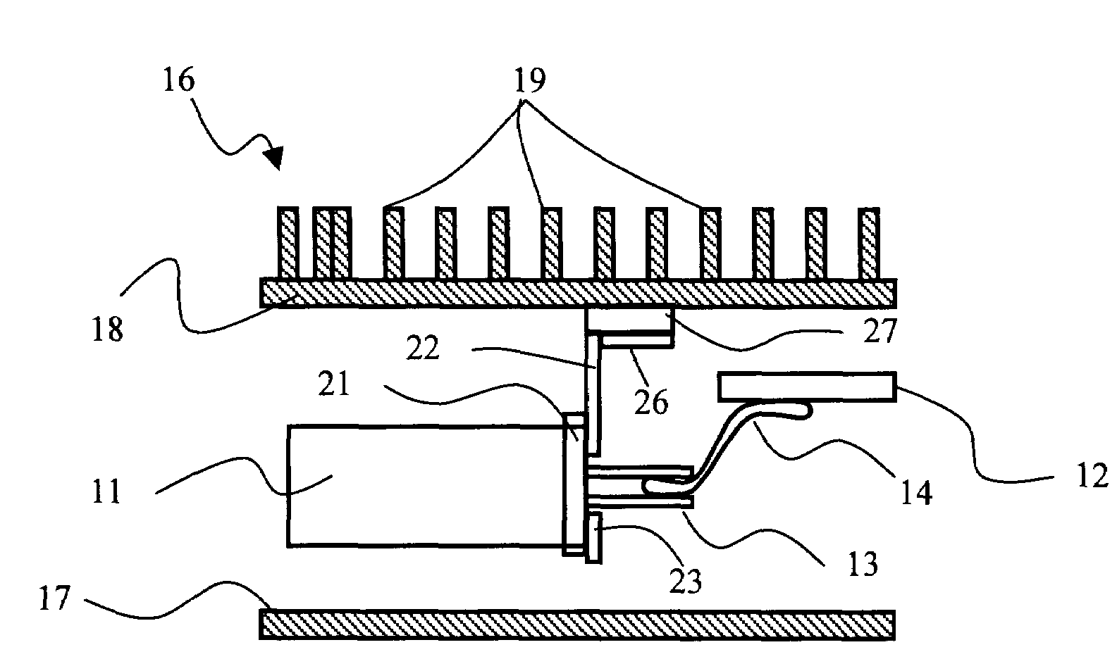
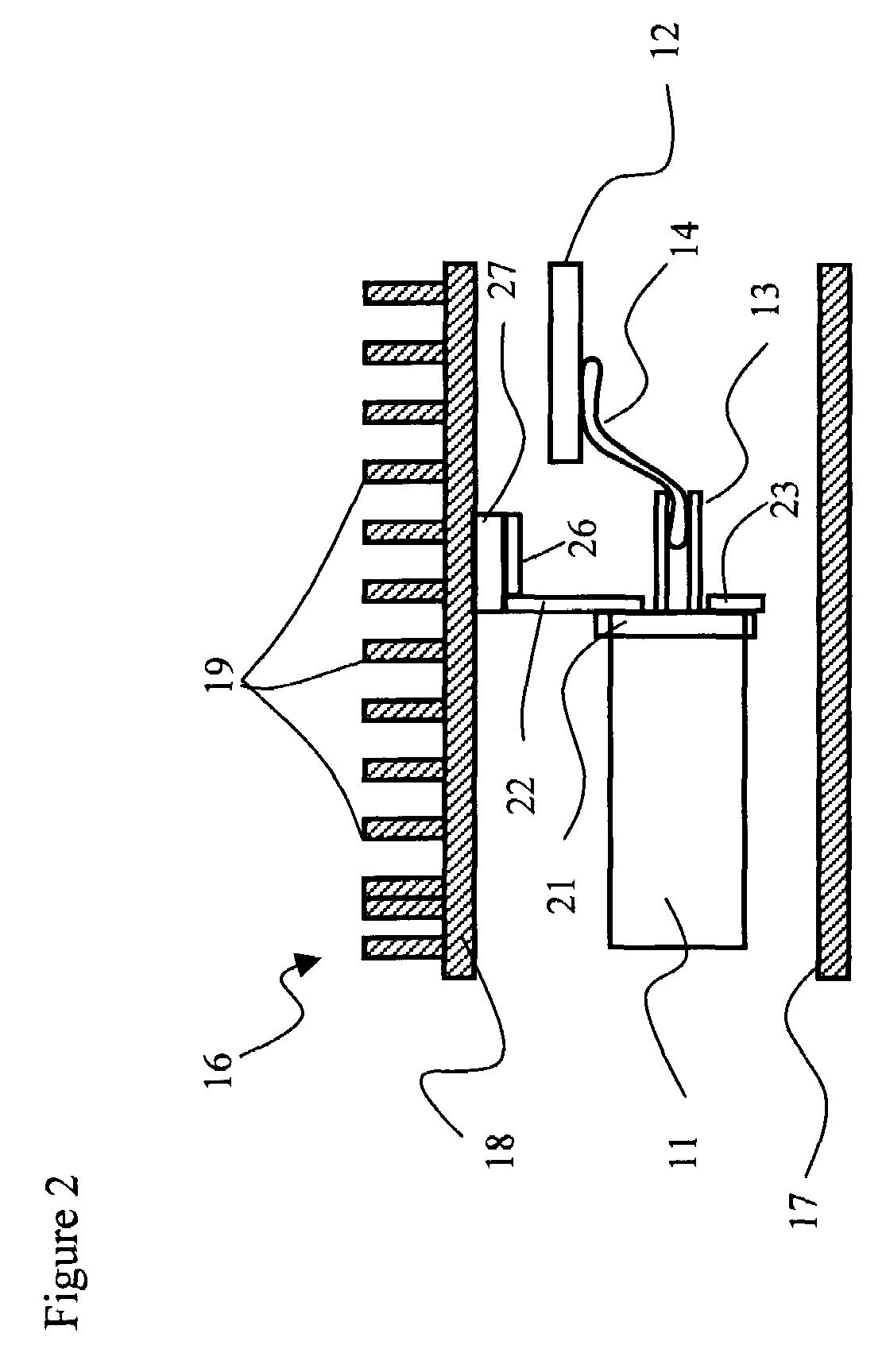
[0025]With reference to FIG. 2, a transceiver according to the present invention includes a TOSA (not shown) and a ROSA 11, which are electrically connected to PCB 12 via metal leads 13 and a flex cable 14. The TOSA and the ROSA 11 include an optical connector on the front end thereof for receiving an end of an optical fiber. A housing 16 encloses the TOSA and the ROSA 11, and includes a lower case 17 and an upper case 18. The upper case 18 includes heat sinking fins 19, although other suitable heat sinking elements are possible, for dissipating heat generated within the housing 16. Typically, an electrical connector is formed on the outer free end of the PCB 12 for electrically connecting the transceiver to a host device, although other electrical connectors, such as pins, are possible.

[0026]Each OSA includes a header 21 extending from the back end thereof, through which the leads 13 extend. A heat sinking tab 22 is mounted on the header 21 with a suitable thermal interface, e.g. s...


PUM


Abstract

The present invention relates to a heat sinking tab for dissipating heat directly from an optical sub-assembly (OSA) to a transceiver housing, within which the optical sub-assembly is located. The heat sinking tab includes a mounting plate for mounting on the rear end of a transistor outline (TO) can, and a finger for extending into contact or close proximity to the transceiver housing. The mounting plate also provides a stiffening plate for flexible conductors used to connect the OSA leads to a transceiver printed circuit board (PCB).

Description

CROSS-REFERENCE TO RELATED APPLICATIONS[0001]The present invention claims priority from U.S. patent application Ser. No. 60 / 539,217 filed Jan. 26, 2004, which is incorporated herein by reference.TECHNICAL FIELD[0002]The present invention relates to a heat sink tab for an optical sub-assembly (OSA), and in particular to a heat sink tab forming a direct thermally conductive path between the OSA and a housing.BACKGROUND OF THE INVENTION[0003]Conventional transceivers include a pair of OSAs, i.e. a transmitter optical sub-assembly (TOSA) (not shown) and a the receiver optical sub-assembly (ROSA) 1, illustrated in FIG. 1. The OSAs are electrically connected to a printed circuit board (PCB) 2 via metal leads 3 or by metal leads 3 and a flexible circuit (flex) cable 4. The OSAs 1 and the PCB 2 are mounted in a transceiver module housing, generally indicated at 6, which comprises a lower case 7 and an upper case 8. Heat sinking fins 9, or other suitable heat sinking elements, e.g. pins, ext...

Claims


Application Information

Patent Timeline
Patent Type & Authority Patents(United States)
IPC IPC(8): G02B7/02G02B6/36G02B7/00G02B26/06G12B15/06H05K5/00H05K7/20
CPCG02B7/008G02B26/06G02B6/4269G02B6/4281G02B6/4283
Inventor HARGIS, MARIAN C.HANLEY, MICHAEL FRANCISMOON, JAMES ROBERT
Owner LUMENTUM OPERATIONS LLC
Learn More